Trusting it is indeed the huuuge problem.
As more people depend on AI less will be able to tell when it's wrong.
As more people depend on AI less will be able to tell when it's wrong.
The internet is an excellent example of trust. How many people become misinformed on various topics? Much is misinformation on purpose.

It's not AI, it's AS -- artificial stupidity. Thing is, there's plenty of that around already.....
And of course the AI engines themselves will start to depend on AI, by consuming their own output, or each other’s, if indeed they aren’t already doing so.As more people depend on AI less will be able to tell when it's wrong.
AI - biggest hoax in IT history. Been going since the early 1950s and has so far produced exactly nothing of value beyond configuring a VAX.
You can do a search here for phono pre. You might find "intelligent" results.
Aside from copying likely a few thousand examples left behind from the 1940's, 50's 60's 70's 80's 90's 2000 on up.
I wonder if a human made one that works within that time frame?
National Semi or later Texas instruments has a few application notes to use a 5532/34 opamp
to create a phono pre.
Aside from copying likely a few thousand examples left behind from the 1940's, 50's 60's 70's 80's 90's 2000 on up.
I wonder if a human made one that works within that time frame?
National Semi or later Texas instruments has a few application notes to use a 5532/34 opamp
to create a phono pre.
Nothing wrong with an NE5534A, maybe a J-Fet front end before that. This will yield higher performance than most and beyond what a cartridge can deliver. Certainly better than the media (record).
There are better, but look at the rest of your system and use something at least that good. It doesn't make sense to use the best phono preamp in the world on a so-so turntable - cartridge combination and a so-so system.
There are better, but look at the rest of your system and use something at least that good. It doesn't make sense to use the best phono preamp in the world on a so-so turntable - cartridge combination and a so-so system.
Nah, it is full of basic errors, designators are complete nonsense, that's nothing to do with what question it was asked, its just doing cargo-cult design, there's no deep understanding, nor even the basics of schematic conventions, and clearly has no idea of what a 100uF capacitor does! See "CL7"...Everybody here should be careful with their replies if they do not know how the specific question to AI looked like. Essentially you get what you asked for.
Unless the AI can go through all the bad circuits in "The Art of Electronics" and explain why each is faulty, its not worth using!!
Here's a thought though - take that circuit design and use in another query to the same AI, asking "what is wrong with this circuit?" - that might be illuminating.
Thanks for all the fine help and discussion, it was an attempt to use a tool, and try to understand some electronics in the process of having a conversation with the group all while testing the limits of AI, (ive had success developing very complex python based GUI software with Grok) guess that's too hard to conceive of in an internet forum.
part of the issue is that GROK can't draw, so It's giving me directions on where to wire things. I'm using kiCad fro the first time here so some of this is most likely me. This is how he's giving it to me :
in Right --- C1R (0.1µF) ---+---- R1R (47kΩ) ---- GND | | +---- Base Q1R | | | +---- Emitter Q1R ---+---- R3R (1kΩ) ---- GND | | | | +---- C2R (10µF) --+ | | +---- C3R (0.01µF) --+---- R4R (75kΩ) ---- Base Q2R | | | +---- C4R (0.22µF) --+---- R5R (6.8kΩ) ---- GND | +---- Emitter Q2R ---+---- R7R (1kΩ) ---- GND | | | | +---- C5R (10µF) --+ | | +---- C6R (2.2µF) ---- Vout Right
Hi coacharnold,
I respect that you're trying to learn. But this isn't the way I don't think.
You know what works well? Look at schematics of projects here (threads have a lot of explanation), or commercial products. Those are debugged, they work. Learn the parts and what they do. You really do need to be able to draw and read schematics and this will help you do that. Even being taught in a course requires time and effort.
When you use a tool, simulators or what we might call AI, you have to know enough to tell when they are wrong. You can't manage people unless you know what they should be doing and how it is done. It's the same thing here. No shortcuts.
I remember looking at an ad in Radio Electronics magazine in the 1960's. It was an astable multivbrator (oscillator) using TTL chips. Back then it mystified me, I thought I'd never understand how it worked. Much less that I could design such a simple circuit. It took work, and one day I realized I understood the circuit and I could design my own - and better. Never looked back. Many of you might even remember the ad, it twas for a correspondence school like NRI or something.
This has lower noise than anything Doug Self ever designed. I think it's revolutionary. Audio bloggers will love the new 'Grounded Input Technology' (GIT for short).
😆 🤣
Don't forget it also has grounded output technology (GOT) through a patented new method using the highest grade parts.
Don't forget it also has grounded output technology (GOT) through a patented new method using the highest grade parts.
part of the issue is that GROK can't draw, so It's giving me directions on where to wire things. I'm using kiCad fro the first time here so some of this is most likely me. This is how he's giving it to me :
in Right --- C1R (0.1µF) ---+---- R1R (47kΩ) ---- GND | | +---- Base Q1R | | | +---- Emitter Q1R ---+---- R3R (1kΩ) ---- GND | | | | +---- C2R (10µF) --+ | | +---- C3R (0.01µF) --+---- R4R (75kΩ) ---- Base Q2R | | | +---- C4R (0.22µF) --+---- R5R (6.8kΩ) ---- GND | +---- Emitter Q2R ---+---- R7R (1kΩ) ---- GND | | | | +---- C5R (10µF) --+ | | +---- C6R (2.2µF) ---- Vout Right
Back in the old days, we used to type netlists to enter circuits into a simulator without a graphical interface. Each line specified a reference designator of a component, the nodes it was connected to and the value or model name. For example,
Q1 2 3 4 BC547B
R12 4 0 100
specifies a bipolar transistor called Q1 of the type BC547B with its collector connected to node 2, its base to node 3 and its emitter to node 4, and a 100 ohm resistor from node 4 to node 0. Node 0 was the reference node or datum, usually ground.
This morning my wife stated that the weather news are sometimes a bit dumb and written how it was never before.
I told her thats for sure AI driven - economizing human work power.
I told her thats for sure AI driven - economizing human work power.
If us humans feed AI with nonsense and lies, it will devour it as a substantial ingredient, process it and present the result as a solution for humans to feed upon. This proces is more or less the same as its inventors (humans) process their matters in life.The problem with AI is that it takes everything in as information without any regard for what is correct, wrong or reasonable.
In a sense, it is not Artificial Intelligence but Human Intelligence.
Human Stupidity.It's not AI, it's AS -- artificial stupidity.
(Einstein: "Human Stupidity and the universe are endless, but I'm not sure about the universe.")
@Citizen124032
I agree. We have no influence on this process as citizens.
I agree. We have no influence on this process as citizens.
In essence irrespective what "intelligence" in the future will exist there should be safety that exclusive interaction with humans is possible if desired.
I see this violated by the use of bots on the web giving false impressions.
All accelerated use of AI never follows an informed debate or consent by society.
I see this violated by the use of bots on the web giving false impressions.
All accelerated use of AI never follows an informed debate or consent by society.
Its interesting that every thread which starts with AI optimized design comes up with utter nonsense.
Cause the wrong people keep asking the wrong questions. AI hates analogue as much as it hates humans.
But if, say, the British PM asks how to design an fpga i would expect a brilliant answer.
Just for fun (I've fixed the grounds to see what the actual circuit does):

To be expected, since the bases aren't biased. Even if they were, you'd have two emitter followers one after the other, so no gain. And that's before even getting to the RIAA eq part...
Good advice above. This is the wrong tool for designing circuits or even just learning about electronics. Search the forum, get a good book (e.g. Horowitz & Hill "The Art Of Electronics"), visit Rod Elliott pages, ask questions here. We'll be glad to help.
The purpose of phono preamp is two fold. First, amplify very small signal of tha cartridge, typically 5mV for mm, 0.2mV for mc to line level.
(Please avoid nentioning such and such mc cart with 2 microvolt output, or that mm cart with 20mV output. Yes, there are exceptions.)
Second, correct for non-linear fr response, that is during lp cutting, low fr range was supressed, not to cause cart jump out, and highs lifted above noise. This is backwards corrected by riaa curve to make line level signal with flat response. Like output from cd or fm tuner or reel to reel.
Gain for mm phono pre should be around 40dB, for mc around 60dB.
Designing phono preamp with no gain is just not inteligent, no matter how much arteficial it is.
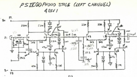
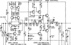
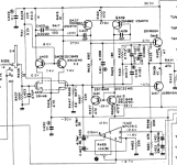
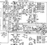
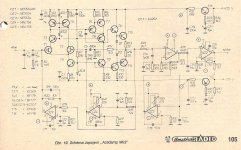
Here are few solid state phono preamps i tried which were designed by human brain, not arteficial stuff.
Although i still have three tube phono preamps, mostly tim deparaviciny clones.
Although i still have three tube phono preamps, mostly tim deparaviciny clones.
Attachments

- Home
- Source & Line
- Analogue Source
- AI Designed Phono Pre-Amp?