Hello all,
I have been working on a phono preamplifier and everything seems about right. But I noticed some occasional harshness in high frequency range.
For example some accented hi-hat of the drums or some high frequencies of vocals get distorted. I checked the PCB and also the RIAA response with measurement software and everything seems about right. The gain at 1KHz is 40dB.
Any thoughts or comment on this?
View attachment 1088418
Last edited by a moderator:

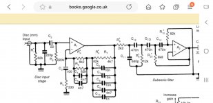
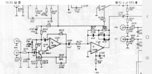
Exactly where the problem is 👍Is the value of C15 suitable for your cartridge and cable? The load capacitance of a moving-magnet cartridge much affects the response above 10 kHz or so.
Actually I removed it after hearing it, nothing changed.
If this is powered by a split supply, get rid of the polarized coupling caps. Use a high quality bi-polar or film cap instead.
And does the op-amp have proper power supply decoupling?
Mike
This is for the circuit, they placed right where the power supply is connected to the board, except the C4 which is placed next to the op-amp.
What cartridge is this, and what's the capacitance of the entire cable run?Exactly where the problem is 👍
Actually I removed it after hearing it, nothing changed.
Anyway, the distortion you are hearing may very well be real, in the sense of being caused by a dirty stylus, mistracking or worn vinyl. Let's put it that way, this is not the ideal medium if you are allergic to treble distortion.
If you want to exclude the preamp as the culprit, you can always build / buy an inverse RIAA circuit and take some loopback measurements. Anything plainly audible should be dead obvious in the distortion department.
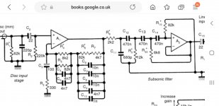
What I did notice is that output loading in the treble is a tad on the heavy side, even for a fairly robust output driver like a 5532... I would add a series resistor for the feedback network (i.e. between it and pin 1) for a "Neumann pole", 50-100 kHz somewhere.
Also, a single input capacitor is too little RF filtering for the input in any high RF environment. Technics phono amps used to have CLC filtering, I bet those would have been quite robust (other manufacturers would often contend themselves with excessive input capacitance like 470 pF or 1000 pF to meet EMC regulations). Another common measure you see in phono preamps is a small capacitor between pins 2 and 3, but note that this also drains some GBW. So if the thing ever acts like a radio, you'll know what to do.
The turntable is a vintage Technics SL-1200 type I from 1972 and the cartridge is Ortofon 2M Red. For your information I have not been using them for about 3 years until I made the phono stage I tried them on.What cartridge is this, and what's the capacitance of the entire cable run?
Anyway, the distortion you are hearing may very well be real, in the sense of being caused by a dirty stylus, mistracking or worn vinyl. Let's put it that way, this is not the ideal medium if you are allergic to treble distortion.
If you want to exclude the preamp as the culprit, you can always build / buy an inverse RIAA circuit and take some loopback measurements. Anything plainly audible should be dead obvious in the distortion department.
What I did notice is that output loading in the treble is a tad on the heavy side, even for a fairly robust output driver like a 5532... I would add a series resistor for the feedback network (i.e. between it and pin 1) for a "Neumann pole", 50-100 kHz somewhere.
Also, a single input capacitor is too little RF filtering for the input in any high RF environment. Technics phono amps used to have CLC filtering, I bet those would have been quite robust (other manufacturers would often contend themselves with excessive input capacitance like 470 pF or 1000 pF to meet EMC regulations). Another common measure you see in phono preamps is a small capacitor between pins 2 and 3, but note that this also drains some GBW. So if the thing ever acts like a radio, you'll know what to do.
R6 and C21 make a low-pass filter with cut-off frequency on 60KHz. Also I checked re response with Rightmark measurement software and the RIAA response is totally fine.What cartridge is this, and what's the capacitance of the entire cable run?
Anyway, the distortion you are hearing may very well be real, in the sense of being caused by a dirty stylus, mistracking or worn vinyl. Let's put it that way, this is not the ideal medium if you are allergic to treble distortion.
If you want to exclude the preamp as the culprit, you can always build / buy an inverse RIAA circuit and take some loopback measurements. Anything plainly audible should be dead obvious in the distortion department.
What I did notice is that output loading in the treble is a tad on the heavy side, even for a fairly robust output driver like a 5532... I would add a series resistor for the feedback network (i.e. between it and pin 1) for a "Neumann pole", 50-100 kHz somewhere.
Also, a single input capacitor is too little RF filtering for the input in any high RF environment. Technics phono amps used to have CLC filtering, I bet those would have been quite robust (other manufacturers would often contend themselves with excessive input capacitance like 470 pF or 1000 pF to meet EMC regulations). Another common measure you see in phono preamps is a small capacitor between pins 2 and 3, but note that this also drains some GBW. So if the thing ever acts like a radio, you'll know what to do.
I think the point is that due to the rather low impedance of the feedback network, the op-amp might go into current limiting for loud high audio frequency signals.
I doubt if that's true, though. An NE5532 can deliver at least 20 mA peak if I remember well. If all of that would flow through the feedback network, it would correspond to 1.42 V peak across R5, which also means 1.42 V peak (about 1 V RMS in the case of sine waves) at the input. In fact some current is needed for R6, so it will be a bit less than 1.42 V peak, but still more than a cartridge normally produces.
I doubt if that's true, though. An NE5532 can deliver at least 20 mA peak if I remember well. If all of that would flow through the feedback network, it would correspond to 1.42 V peak across R5, which also means 1.42 V peak (about 1 V RMS in the case of sine waves) at the input. In fact some current is needed for R6, so it will be a bit less than 1.42 V peak, but still more than a cartridge normally produces.
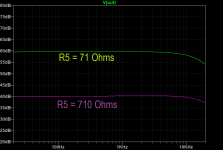
The gain is [1+ (R2||R9+R1||R10)]/R5 ~ 60dB, not 40dB so you have run out of "over-head margin. Make R5 710 Ohms.Hello all,
I have been working on a phono preamplifier and everything seems about right. But I noticed some occasional harshness in high frequency range.
For example some accented hi-hat of the drums or some high frequencies of vocals get distorted. I checked the PCB and also the RIAA response with measurement software and everything seems about right. The total gain of the circuit is 40dB.
Any thoughts or comment on this?
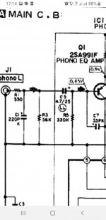
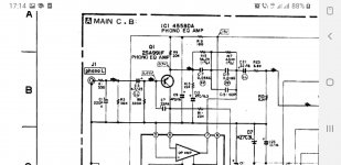
He'd better copy D Self .The input resistor loading is split for a reason.56k || 330k are better values instead of 62k||220K or 100k||100k, but that works for a lower current noise input than ne5534.I'm working on a composite with lm394 replacing the input pair in Ne5534 where I'll try 470k....680k bias resistor. The internal input trz of ne5532/34 have 12...13kohm collector resistors so their hfe need to be pretty high for a higher value than 220k ohm bias resistor.With one stage opamp active riaa you win on SNR, but you need to give back a little through input current noise because you can't afford the minimum theoretical supply of +- 22.5 v that few op amps designed for riaa could take.
D self was mocked a lot by people ignoring some little tricks up his sleeve, but to my knowledge the only true clone of his preamp talked about here was done by @ Molly back in 2009.
D self was mocked a lot by people ignoring some little tricks up his sleeve, but to my knowledge the only true clone of his preamp talked about here was done by @ Molly back in 2009.
Attachments
-
 Screenshot_20220906-225650_Samsung Internet.jpg94.7 KB · Views: 171
 -
 Screenshot_20220906-230214_Samsung Internet.jpg103.1 KB · Views: 174
 -
 Screenshot_20220907-171411_Word.jpg93.3 KB · Views: 155
 -
 Screenshot_20220907-171447_Word.jpg119.9 KB · Views: 155
 -
 Screenshot_20220905-104557_Word.jpg143.1 KB · Views: 165
Last edited:
My mistake, at 1KHz gain is the conventional 40dBThe gain is [1+ (R2||R9+R1||R10)]/R5 ~ 60dB, not 40dB so you have run out of "over-head margin. Make R5 710 Ohms.
* Testing beats guessing any day of the week.Hello all,
I have been working on a phono preamplifier and everything seems about right. But I noticed some occasional harshness in high frequency range.
For example some accented hi-hat of the drums or some high frequencies of vocals get distorted. I checked the PCB and also the RIAA response with measurement software and everything seems about right. The gain at 1KHz is 40dB.
Get an Audio Test LP , play it and scope output.
* why those monster input and output coupling caps?
Electrolytic or not I would not use above, say, 1uF at input (which would still be 3.4Hz hipass) and 10uF at output which would still be around 8Hz for an incredibly low load of 2K.
I would actually expect next stage to be at least 10k anyway.
I appriciate it man, you helped a lot 🙏Note the change in R5:
These were very helpful information, thanks alot 🙏He'd better copy D Self .The input resistor loading is split for a reason.56k || 330k are better values instead of 62k||220K or 100k||100k, but that works for a lower current noise input than ne5534.I'm working on a composite with lm394 replacing the input pair in Ne5534 where I'll try 470k....680k bias resistor. The internal input trz of ne5532/34 have 12...13kohm collector resistors so their hfe need to be pretty high for a higher value than 220k ohm bias resistor.With one stage opamp active riaa you win on SNR, but you need to give back a little through input current noise because you can't afford the minimum theoretical supply of +- 22.5 v that few op amps designed for riaa could take.
D self was mocked a lot by people ignoring some little tricks up his sleeve, but to my knowledge the only true clone of his preamp talked about here was done by @ Molly back in 2009.
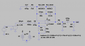
The RIAA values used in Alavala's circuit are similar to the ones I use in my designs. The gain of the one below is 75x or c. 37.5 dB. You may want to try a OPA1641 for the main gain element for improved RFI and because you can omit the 470uF cap shown in the circuits above since the OPA1641 bias currents are very low. You will end up with a worst case output offset of about +-300mV because the EQ network will be DC coupled, but that is easily taken care of with a DC blocking capacitor to the following stage. Normally you wouldn't add additional capacitance on the input of an RIAA, but rather adjust the load resistance to mitigate the possible HF peaking due to the cartridge interaction with the cable capacitance (50-100pF per meter)- there's quite some discussion on this in another thread for those that are interested. For the circuit shown below, you can adjust R13 from a low of 50 Ohms all the way up to 270 Ohms and still get good RIAA conformance - the conformance sweet spot is 120 to 150 Ohms at about +-0.2dB 20 Hz to 20 kHz. R11 flattens the response in the midband. The RIAA values were calculated based on Stanley Lipshitz's 'On RIAA Equalization Networks' paper. For C2 I use a 12nF//820pF. All EQ caps are NP0/COG 1% except for the 820pF which is 5%.
The opamp output current feeding into the EQ network at HF (20 kHz) with an input of 2V is 20mA. For normal signal levels its about 20 dB lower than this so there isn't a problem practically with this - you should be good to go.

The opamp output current feeding into the EQ network at HF (20 kHz) with an input of 2V is 20mA. For normal signal levels its about 20 dB lower than this so there isn't a problem practically with this - you should be good to go.
Last edited:
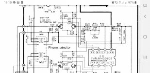
R11 does the same as R123 in Technics su V6 , isn't it?R11 flattens the response in the midband. The RIAA values were calculated based on Stanley Lipshitz's 'On RIAA Equalization
View attachment 1088625
- Home
- Source & Line
- Analogue Source
- Advise needed on a phono preamp (occasional harshness in high frequency range)