Thanks Juhazi. I will try out the suggestions and see how that goes.
3.5KHz might be too high due to C2C concern and directivity matching, but i will give that a shot to see if i prefer that.
You have a large metal midrange with a massive resonance. A 3.5kHz crossover is not sensible although, perversely, I think it is worth trying to help get some sort of handle on the relative size of things. If you try it and it doesn't change much compared to what you are picking up on that would be a clue.
Can you please show us the impulse response of the FIR filters you are using on the mid and tweeter. The reason I have been asking is to rule out significant amounts of preringing which will not be apparent in the frequency responses but can be audible if present in large amounts. Preringing means the tweeter and midrange start moving in opposite directions before the signal arrives. Mathematically on-axis they should cancel but off-axis they won't and even on-axis one or two real world considerations can intrude. It doesn't matter in small quantities and is fixable in large quantities but a check is probably worthwhile.
I must apologise for not noticing the dip between 300Hz and 1kHz. This is certainly not going to be helping things and will definitely give a mid-forward presentation.
Yes Matt, that is a possibility. Having heard Lx521, Lxmini both of which have an upper midrange driver or full range driver covering a good part of high freq that i can hear might just be something i prefer versus how a traditional dome sounds at that job.
But it is the occasional harshness than has perplexed me. Something subtle could be off, but hard to investigate without tools and time.
Btw, the 9018 DAC itself is every bit as good as you had suggested it would be. Very clean and transparent.
Just a thought, if you like to hear how your speaker sounds with mid/tweeter XO point upped to area 3-7kHz Madisound and PartsExpress have Tymphany TC9FD18-08 at only $13. Orange in below plot show W15 and present pass-band from post 407, blue is 10F/8424, green 10F/8414, and lime is TC9FD. Three of them is traced from manufactures datasheet and TC9FD is traced from Zapp's blog.
Attachments
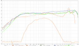
Just a thought, if you like to hear how your speaker sounds with mid/tweeter XO point upped to area 3-7kHz Madisound and PartsExpress have Tymphany TC9FD18-08 at only $13. Orange in below plot show W15 and present pass-band from post 407, blue is 10F/8424, green 10F/8414, and lime is TC9FD. Three of them is traced from manufactures datasheet and TC9FD is traced from Zapp's blog.
BYRTT,
This thought had crossed my mind, but with the similar full range driver used in Lxmini. I had to set aside the plan, because currently the tweeter shares enclosure with the two 8" woofers and this mod would require me to add a good sealed enclosure behind the full range driver.
You have a large metal midrange with a massive resonance. A 3.5kHz crossover is not sensible although, perversely, I think it is worth trying to help get some sort of handle on the relative size of things. If you try it and it doesn't change much compared to what you are picking up on that would be a clue.
Can you please show us the impulse response of the FIR filters you are using on the mid and tweeter. The reason I have been asking is to rule out significant amounts of preringing which will not be apparent in the frequency responses but can be audible if present in large amounts. Preringing means the tweeter and midrange start moving in opposite directions before the signal arrives. Mathematically on-axis they should cancel but off-axis they won't and even on-axis one or two real world considerations can intrude. It doesn't matter in small quantities and is fixable in large quantities but a check is probably worthwhile.
Andy,
Ah yes i had missed that the massive resonance (even though sharply notched out by DSP) is another reason why a high XO is difficult. The drivers harmonic distortions also sharply rise around the breakup region.
But i will try this out to see how the change sounds to my preference.
I will post the impulse response of the mid/tweeter filters.
I must apologise for not noticing the dip between 300Hz and 1kHz. This is certainly not going to be helping things and will definitely give a mid-forward presentation.
Matt,
That dip, its about 1-1.5db. It is something easy to fix so will do that.
Just a thought, if you like to hear how your speaker sounds with mid/tweeter XO point upped to area 3-7kHz Madisound and PartsExpress have Tymphany TC9FD18-08 at only $13. Orange in below plot show W15 and present pass-band from post 407, blue is 10F/8424, green 10F/8414, and lime is TC9FD. Three of them is traced from manufactures datasheet and TC9FD is traced from Zapp's blog.
But with that response and price that is a nice little driver. I had put them in my list of good performing drivers the last time you pointed it out.
sorry, havnt found time to try out all the suggested options. But made following changes.
1. Fixed the dip between 300Hz - 1KHz
2. MT XO changed to 3KHz LR8
I think i do prefer this more, the upper ranges do sound a bit more relieved now. But this could just be my head. I will listen to this setup for a few days and then post to confirm.
1. Fixed the dip between 300Hz - 1KHz
2. MT XO changed to 3KHz LR8
I think i do prefer this more, the upper ranges do sound a bit more relieved now. But this could just be my head. I will listen to this setup for a few days and then post to confirm.

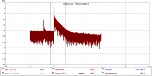
What is that a plot of? Would like to see a conventional impulse response windowed to show the degree of motion before the impulse arrives. However, the plot does suggest motion a long time before the impulse arrives which is not good. The motion might be low in level (is it?) but any coefficient calculating algorithm that creates motion a long time before the impulse arrives is a concern.IR of Mid and tweeter driver measurements with filters.
What is that a plot of? Would like to see a conventional impulse response windowed to show the degree of motion before the impulse arrives. However, the plot does suggest motion a long time before the impulse arrives which is not good. The motion might be low in level (is it?) but any coefficient calculating algorithm that creates motion a long time before the impulse arrives is a concern.
These are from a full range sweep measurement of the loudspeaker using REW.
All channels except the tweeter or mid is muted. REW can then display the impulse response from the test.
Are the smaller pulses before the impulse at 0 what you are referring to as early motion?
Just some food for thought.
Measuring the low frequencies in a typical room isn't easy.
Luckily that doesn't matter as the laws of physics dictate the entire behaviour of the loudspeaker.
At low frequencies your bass driver is going to be operating as a pure piston, breakup will not have occurred yet and there will also be no diffraction effects to worry about.
If you ignore the effects of baffle step then the driver will have a completely flat frequency response. This is shown quite effectively in SEAS own measurements. In SEAS measurements the driver exhibits baffle step losses but is otherwise completely flat up to just under 2kHz.
I am not entirely sure what your targeted crossover point for the woofers low end is but there is a fairly simple way of designing a crossover for it.
1) Apply a textbook crossover for whatever your target slope may be, for example a 4th order Linkwitz Riley (Q of 0.5) at 300Hz.
2) Apply a textbook filter for the correction of baffle step using the cabinet width as a guide.
The woofers are sealed right? And crossover to the sub woofer using active filtering. If so...
3) Calculate/measure and do whatever is necessary to find out what the Qtc and corner frequency for the woofers alignment is. Near field measurements/impedance plots etc.
4) Lets say you are crossing over at 60Hz with 4th order LR slopes to the subs. Apply a Linkwitz Transform circuit to the woofers. Use your measured/calculated Qtc and f3 for the actual figures and set the target Qtc to 0.7 and the f3 to 60Hz.
5) Apply a 2nd order textbook Butterworth highpass filter (Q = 0.7) with an f3 of 60Hz.
If you do this the actual measured response from the woofers will be very close to reality. The only thing you'll be left needing to fine tune is the amount of baffle step compensation needed and the absolute level of the woofers.
The same approach can be taken for the high pass filter of the midrange driver.
1) Calculate/Measure the actual Qtc and corner frequency of the W15CY001 within your cabinet.
2) Apply a Linkwitz Transform using the parameters from above and set the target parameters to your desired high pass. For example if you are wanting a 300Hz LR set the target parameters on the LT to 300Hz with a Q of 0.7.
3) Apply a 2nd order Butterworth filter with a Q of 0.7 and an f3 of 300Hz.
This will pretty much guarantee that the high pass characteristics of the W15CY001 are what you want them to be.
4) Apply a text book baffle step compensation filter to the midrange using the baffle width as your guide for the centre frequency of the compensation filter.
Interestingly you can also take a similar approach to the tweeter xover. The T25CF001 is of course its own little sealed loudspeaker. SEAS tells us the resonance is at 700Hz. If you perform some near field measurements and compare the lower end roll off of the tweeter to some generated 2nd order slopes with a corner frequency of 700Hz and then vary the Q until they match you'll have your figures. Then simply plug the 700Hz + whatever the measured Q is into a LT filter, set the target parameters of the LT to say 2000Hz with a Q of 0.7, then apply a 2nd order high pass of Q 0.7 and f3 of 2000Hz. This will give you a theoretical perfect 4th order LR with a corner frequency of 2000Hz. Of course this will not take into consideration the effects of diffraction but you could correct for those with notch filters or inverse notches.
I'm not sure if you can construct LTs using the filter set you've got? But they can be incredibly useful when you want to try a different approach.
An impulse response shows the response of the driver to an impulse as an input. It is plot of pressure vs time and typically shows a spike with some wiggles with both positive and negative values. Your plot appears to have a log y axis (cannot log negative values), no values at minus infinity, grass before the impulse with a range of roughly -100 to -60 but after the impulse the maximum value of the grass falls below -60. It seems to be related to an impulse response but I don't know how and when checking for mistakes it is important to know precisely what you are looking at.These are from a full range sweep measurement of the loudspeaker using REW.
All channels except the tweeter or mid is muted. REW can then display the impulse response from the test.
Are you able to plot the actual impulse response in a window showing the height of the pulse and for a time range covering 10-20 time periods of the crossover frequency before the impulse and after. What we are looking for is significant motion before the impulse that would turn the sound of a click into more of a chirp which might well line up with a loss of clarity you are reporting hearing. Wiggles at the sampling frequency are less important.
The bumps out of the grass half a second before the impulse are suggestive of something being broken. A driver that is reacting to a sound half a second before it occurs is obviously wrong. But we don't really know what we are looking at because it is not the raw data (e.g. the coefficients) but a processed measurement of some kind. It might be an artifact of that measurement processing. It looks wrong and significantly so making further investigation worthwhile to find the cause and fix it if it is real.
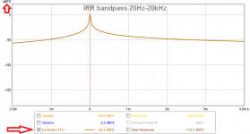
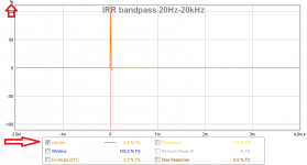
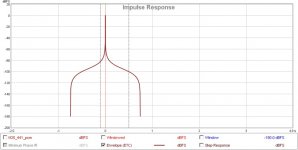
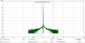
Thanks for that. I was looking for something like the one on the right if m is for msec. It will not show the problem at -0.5 sec but will hopefully show if there is a click to chirp issue.jojip plots show "Envelope (ETC)" and scale is "dB FS", guess you like them presented as "Impulse" and scale as "% FS".
Below example is how 20Hz-20kHz band-pass device looks into those two presentation settings.
BYRTT,
This thought had crossed my mind, but with the similar full range driver used in Lxmini. I had to set aside the plan, because currently the tweeter shares enclosure with the two 8" woofers and this mod would require me to add a good sealed enclosure behind the full range driver.
But with that response and price that is a nice little driver. I had put them in my list of good performing drivers the last time you pointed it out.
Think we think in two different scenarios here : )
Yours seems to use full ranger in Lxmini-way as single mid/tweet to replace both W15CY and T25CF001 and therefor you plan place it into tweeter enclosure.
My thought was only to replace W15CY with a driver that seems also can fulfill low frq corner (LR4 300Hz or higher) as seen into plot at post 423 but have break up nastiest much higher than W15CY so XO to tweeter can be tested higher in frq as talked about. Pointed to TC9FD because of its fantastic low cost and if relieved by a tweeter in 3-7kHz area think it will perform as fine as much more expensive 10F/8424, also member Barleywater show very impressive data with TC9FD (in a Lxmini build) here in diyA domain, and thought for mounting was same enclosure as W15CY and make adaptor with outer diameter as W15CY and mount TC9 inside this adaptor and if possible maybe offset it little bit downward closer to tweeter.
Last edited:
I am not at all worried about that W15 cone resonance with dsp/eq and LR4 at 3,5kHz. But give it a try!
SEAS 5INCH
SEAS 5INCH
- Status
- Not open for further replies.
- Home
- Loudspeakers
- Multi-Way
- Advice needed on 4 Way loudspeaker