6.8 k resistor is feedback. This has no feedback from the output past the capacitor.I belive the feedback must be messed up somehow, if I pull the 1Mohm resistor that should remove the feedback right?
I've built the 6 transistor AX6 post #8 link to my actual schematic. Doesn't produce square waves, produces nice music. Sounds like my CS800s at <70 watts. I built point to point since the prototype board post 1 won't fit in my ST120 case. But I soldered the wires, not rely on a push in board. Mine produces 70 w @ 69 v rail, don't know what it would do on 30 v rail.
Class A amp previous post is direct coupled to speaker, can burn driver if a wire pops loose & DC comes out. My drivers are >$200 each, I like the $3 capacitor protecting my speaker from DC current. Most $5 relay protection kits are snake oil: will weld the relay contacts closed if a big current dump comes through a shorted output transistor. 99.9% of schematics on solid state forum are direct coupled transistor to speaker: not safe for people that make actual bad solder joints(me), or worse, push in connections.
Last edited:

Your mileage may vary, but I don’t actually own any loudspeakers that would be harmed by a temporary application of 15 volts DC. Some raw drivers, yes - but that’s a midrange, and I don’t know how to build a band pass network without a cap in series somewhere. All the BIG stuff uses ice cube relays capable of breaking 20+ amps DC, and a couple medium power units use output caps.
I'll be using a 11600uF coupling cap on the output no matter what I build, puts the - 3dB cutoff at about 3.5Hz. This will be soldered straight to a full range element and I want that sub bass but to also not torch the coil 🙂
I'll try pulling that resistor then, probably not going to be very linear but it's hopefully going to remove some of the issues. I'll probably build it more permanently if so and add a pot instead of the 6.8kohm 🙂6.8 k resistor is feedback. This has no feedback from the output past the capacitor.
I've built the 6 transistor AX6 post #8 link to my actual schematic. Doesn't produce square waves, produces nice music. Sounds like my CS800s at <70 watts. I built point to point since the prototype board post 1 won't fit in my ST120 case. But I soldered the wires, not rely on a push in board. Mine produces 70 w @ 69 v rail, don't know what it would do on 30 v rail.
Class A amp previous post is direct coupled to speaker, can burn driver if a wire pops loose & DC comes out. My drivers are >$200 each, I like the $3 capacitor protecting my speaker from DC current. Most $5 relay protection kits are snake oil: will weld the relay contacts closed if a big current dump comes through a shorted output transistor. 99.9% of schematics on solid state forum are direct coupled transistor to speaker: not safe for people that make actual bad solder joints(me), or worse, push in connections.
Whilst I do have caps that big, it's two 5800uF ones in parallel 🙂Where did you manage to salvage an 11600 uF cap? Or is it really two 4700’s and a 2200?
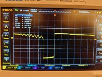
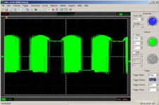
Here is an example of the output I'm getting to my dummy 4ohm load at the moment, looks like some ringing or something. This is with 10mVrms 1kHz input. At 100mVrms in its just a square wave.
I think part of the issue might be that I substituted the BC560 with a BC557B which doesn't have as much current gain. I just expected it to need more drive signal but that might be an incorrect assumption.
If I pull the 6.8Kohm resistor the amp does nothing. No current drawn or anything.
I think part of the issue might be that I substituted the BC560 with a BC557B which doesn't have as much current gain. I just expected it to need more drive signal but that might be an incorrect assumption.
If I pull the 6.8Kohm resistor the amp does nothing. No current drawn or anything.
Attachments
To me it smells like the amp is operating open loop without proper feedback, which would indicate a wiring error. Check the voltages at the emitters of the first two stages, and determine if they make sense. The amp has both DC and AC feedback - need to get the DC feedback working first.
We may have to analyze what you’re seeing and compare to what you should have gotten. One common problem with these single supply amplifiers is that they often misbehave if run significantly away from the power supply voltage it was designed for. The DC often does not center correctly making troubleshooting more difficult. And might require fiddling with to optimize once the real problems are ironed out.
And 2N6123’s burning up trying to run on 50 volts doesn’t surprise me either - even if it was working properly. You‘d want at least the TIP33/34 pair to run that high.
Gain of the input transistor should be set by the resistor values. What does the waveform look like at the emiitter of the input transistor? Is DC value 3.7 v? 3.1 vdc at the VAS (2nd transistor)? 23.9 vdc at the base of the lower driver?
2n6123 crosses to RCA3024 which is 80 v vceo TO39 case. TO39 case is pretty wimpy for output transistors, and you would need a heat sink on any output transistors.
2n6123 crosses to RCA3024 which is 80 v vceo TO39 case. TO39 case is pretty wimpy for output transistors, and you would need a heat sink on any output transistors.
Last edited:
I have pretty phat heatsinks now, used too small ones at first and that's probably why the 2N6123s died, but these keep everything nice and cool. I haven't checked those DC values today and I don't remember what they were yesterday.Gain of the input transistor should be set by the resistor values. What does the waveform look like at the emiitter of the input transistor? Is DC value 3.7 v? 3.1 vdc at the VAS (2nd transistor)? 23.9 vdc at the base of the lower driver?
2n6123 crosses to RCA3024 which is 80 v vceo TO39 case. TO39 case is pretty wimpy for output transistors, and you would need a heat sink on any output transistors.
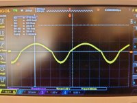
Swapped the input transistor from a BC557B to a BC252C and everything is working much much better. Output is sinusoidal up until about 30mVrms and then it starts clipping, but the output is still not right. The top part of the wave is stretched and the bottom is squished together. Period is still correct though. Extremely strange distortion, I've never seen anything like that before myself
The 2N6123s are TO-220 package, the rest TO-92
At 50V rail all the DC voltages seem to be within 200mV of their specified values, that could be me not having the PSU dialed to a perfect 50V. The output still has the same distortion at 30 and 50V, even all the way down to about 10V rail the output is the exact same with 10mVrms 1kHz input.
Attachments
Looks like the center is off center. What voltage is the junction of 6k8 and 100 uf cap with the rail voltage reading at the same time? Input shorted.
You also have some crossover distortion. What is voltage across upper .47 ohm resistor with music input shorted?
You also have some crossover distortion. What is voltage across upper .47 ohm resistor with music input shorted?
Well...
It just stopped working in the breadboard suddenly, no matter what I swapped, so I just built the best working configuration, which is what I was showing the waveforms from, in some protoboard because I was almost certain it was the capacitance screwing with stuff and yep. I was right. It now works beautifully up until about 105mVrms input.
100mVrms input at 30V rail gives 7V over a 4ohm load so 12.25W.
With more rail voltage it should be able to produce more power but I'll probably call it here, I reached the 10-20 watt range I was aiming for and I can get more with ease. Will have to implement an attenuator between the BT module and this amp but that's just a couple of resistors 🙂
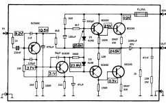
The final configuration for anyone who might want to replicate(or for me when I've forgotten in some years 😂):
BC560C swapped for BC252C
BC639 swapped for BC337-16
BC640 swapped for BC327
BD243 swapped for 2N6123
No other components swapped
Schematic attached for future reference
Rail can be up to 50V depending on what power you want out, I would not go below 20V rail though.
Will post pictures once I put it in a box, thank you so much for all the help!
Edit:
Draws 0.73A at 30V -> 21.9W so 56% efficiency. Not great(pretty much spot on for class AB), but compared to tubes? Absolutely otherworldly 😂
It just stopped working in the breadboard suddenly, no matter what I swapped, so I just built the best working configuration, which is what I was showing the waveforms from, in some protoboard because I was almost certain it was the capacitance screwing with stuff and yep. I was right. It now works beautifully up until about 105mVrms input.
100mVrms input at 30V rail gives 7V over a 4ohm load so 12.25W.
With more rail voltage it should be able to produce more power but I'll probably call it here, I reached the 10-20 watt range I was aiming for and I can get more with ease. Will have to implement an attenuator between the BT module and this amp but that's just a couple of resistors 🙂
The final configuration for anyone who might want to replicate(or for me when I've forgotten in some years 😂):
BC560C swapped for BC252C
BC639 swapped for BC337-16
BC640 swapped for BC327
BD243 swapped for 2N6123
No other components swapped
Schematic attached for future reference
Rail can be up to 50V depending on what power you want out, I would not go below 20V rail though.
Will post pictures once I put it in a box, thank you so much for all the help!
Edit:
Draws 0.73A at 30V -> 21.9W so 56% efficiency. Not great(pretty much spot on for class AB), but compared to tubes? Absolutely otherworldly 😂
Attachments
Last edited:
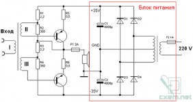
Next problem. The PAM83(4?)03 chip is a BTL class D amplifier. The output is 300-500 kHz square wave. You can use a small 1:1 or step-down transformer.
Attachments
Last edited:
I built an amp using Icepower modules from Parts Express. I used the ICEpower 50ASX2SE modules, which are listed as 50 watts for 4 ohms, but they have others. One nice feature of these amp boards is that they include their own power supply on the same board, so you only need to connect AC, input and output and you are good to go. I built a 4 channel amp using 2 of these modules as a back up amp for when my SE tube amps are on the bench. I was pleasantly surprised at how good they sound.
I mean why not just burn the excess signal in some resistors? I don't have any transformers that will be alright in this application and power efficiency is already not a concern.Next problem. The PAM83(4?)03 chip is a BTL class D amplifier. The output is 300-500 kHz square wave. You can use a small 1:1 or step-down transformer.
Would there be excessive noise?
On output 8403, turn on the load of 10-100 ohms. Remove the mixsignal from one output.RC or active filter with a cutoff frequency of 20 kHz. Otherwise, you run the risk of burning a powerful amplifier with a high frequency (Carrier frequency class D amplifier).Would there be excessive noise?
Attachments
Last edited:
What is meant here is that many of those cute little class D modules do NOT have an output low pass filter. The SPEAKER performs that function, and if you use the output to drive something else a low pass filter is needed to keep all that milti-hundred-kHz hash out of it. One of those little retro amplifiers will not like it. Distort horribly - definitely. Blow up - quite possible.
Problem is I’m not sure an RC filter would be enough. LC, definitely - because that’s what better class D equipment uses. Basically, you need a low pass speaker crossover network at say, 25 kHz. Calaculate it the same way you normally would, and include the load.
Problem is I’m not sure an RC filter would be enough. LC, definitely - because that’s what better class D equipment uses. Basically, you need a low pass speaker crossover network at say, 25 kHz. Calaculate it the same way you normally would, and include the load.
Picked 10nF and 4.7mH for my filter, looked good on the scope. I'll hopefully put this together somewhat more final tomorrow 🙂What is meant here is that many of those cute little class D modules do NOT have an output low pass filter. The SPEAKER performs that function, and if you use the output to drive something else a low pass filter is needed to keep all that milti-hundred-kHz hash out of it. One of those little retro amplifiers will not like it. Distort horribly - definitely. Blow up - quite possible.
Problem is I’m not sure an RC filter would be enough. LC, definitely - because that’s what better class D equipment uses. Basically, you need a low pass speaker crossover network at say, 25 kHz. Calaculate it the same way you normally would, and include the load.
- Home
- Amplifiers
- Solid State
- Advice/inspiration for 10-20W into 4ohm amplifier