Looks like those values will work with a load of around 500 ohms, and a cutoff frequency in the right ballpark.
Well this has been a huge pain to try to integrate.
At first I forgot the attenuator so it didn't work at all, so I added the attenuator and it still didn't work.
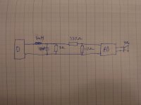
The filter seems to perform much worse with the attenuator, no matter if its placed before or after it. I added the 4 ohm resistor as a load for the D class and it became much happier and gave a better signal but the output to the AB amp still looks like mostly high frequency noise with a trace amount of test signal as ripple barely visible on the scope.
Attached a drawing of the best working version I put together last night, but I haven't actually attached it to the AB amp and I've only looked at the signal over the 10 ohm resistor with my scope.
Pretty sure I'm just blind for my own mistake at the moment so hopefully someone can tell me why it's working so poorly 😅
At first I forgot the attenuator so it didn't work at all, so I added the attenuator and it still didn't work.
The filter seems to perform much worse with the attenuator, no matter if its placed before or after it. I added the 4 ohm resistor as a load for the D class and it became much happier and gave a better signal but the output to the AB amp still looks like mostly high frequency noise with a trace amount of test signal as ripple barely visible on the scope.
Attached a drawing of the best working version I put together last night, but I haven't actually attached it to the AB amp and I've only looked at the signal over the 10 ohm resistor with my scope.
Pretty sure I'm just blind for my own mistake at the moment so hopefully someone can tell me why it's working so poorly 😅
Attachments
How BIG is the inductor, physically? If it was designed for a 4 ohm woofer crossover, you may be above its self resonant frequency. You may have to use a cored high frequency inductor. When used at a higher impedance level the current isn’t very high so saturation isn’t as much as an issue as when filtering speakers. OTOH, if you put a 4 ohm load on it you need filter values for 4 ohms, which will be in the 20 uH and maybe .1 uF range. Easy to make an air core or low mu toroid that will do the trick.
I recommend a half-wave balanced complementary transistor push-pull amplifier like Hiraga's Classe A.
You can also build this without a circuit board;-)
https://sound-au.com/tcaas/hiraga.htm
You can also build this without a circuit board;-)
https://sound-au.com/tcaas/hiraga.htm

It's a small high frequency inductor with a ferrite core and box. About 1.5x1x0.5 cm in size. Cap is a small ceramic one. Another thing is that the filter seems to work a bit better before the attenuator than when placed after it, even with the 4 ohm load as drawn.How BIG is the inductor, physically? If it was designed for a 4 ohm woofer crossover, you may be above its self resonant frequency. You may have to use a cored high frequency inductor. When used at a higher impedance level the current isn’t very high so saturation isn’t as much as an issue as when filtering speakers. OTOH, if you put a 4 ohm load on it you need filter values for 4 ohms, which will be in the 20 uH and maybe .1 uF range. Easy to make an air core or low mu toroid that will do the trick.
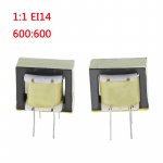
Transformer 600:600 ohm. https://aliexpress.ru/popular/audio-transformer-600-ohm.html?g=n&page=2
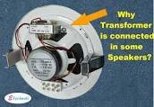
Ceiling speaker transformer 70v. https://www.alibaba.com/showroom/speaker-with-70v-100v-transformer.html
https://aliexpress.ru/item/10050019...lts.5.1b4b14a73US53O&sku_id=12000018269454741
Ceiling speaker transformer 70v. https://www.alibaba.com/showroom/speaker-with-70v-100v-transformer.html
https://aliexpress.ru/item/10050019...lts.5.1b4b14a73US53O&sku_id=12000018269454741
Attachments
Last edited:
Well after playing around some with different components for the filter, both in simulator and physically, the PAM8403 chip has died... Not really sure why, I just heard the PSU start screaming and slammed the power off and some poking around discovered a very warm and slightly charred chip 🙃
Hoping it didn't take the BT recover part with it and that the BT reciver has an analog output I can just hijack instead :/
Hoping it didn't take the BT recover part with it and that the BT reciver has an analog output I can just hijack instead :/
Well well well! Lucky me! The rest of the board lived and the signal into the PAM8403 was exactly in the range that the amp i built in this thread likes as input!
Nice to not have to deal with any filter, the signal is exceptionally clean at all playback levels. Just have to throw together a stereo to mono thing and i should be good to go i think 🙂
Nice to not have to deal with any filter, the signal is exceptionally clean at all playback levels. Just have to throw together a stereo to mono thing and i should be good to go i think 🙂
Hooked it up, worked perfectly right away! Like it was ment to be, sounds exactly like i hoped and i didnt loose the low end 😀
Just under 18W into a 4 Ohm load at 1kHz with 48V rail and about 1.5W power consumption when not playing anything. Extremely happy with this whole thing, now i just need to finish mounting everything properly and building my speaker 😀
Just under 18W into a 4 Ohm load at 1kHz with 48V rail and about 1.5W power consumption when not playing anything. Extremely happy with this whole thing, now i just need to finish mounting everything properly and building my speaker 😀
Last edited:
- Home
- Amplifiers
- Solid State
- Advice/inspiration for 10-20W into 4ohm amplifier