Hello,
After reading the old thread I wanted to start a new one because there will be new questions and probably new ideas too.
In the old thread some people start talking about changing the wima caps in the digital part by 100nF kemet PPS caps and the 10microfarad cap by a Sanyo os con.
Some other member did ask Doede and this info was forwarded to me.
C6 and C15 are the most import ones. C11 and C 12 Doede wouldn't care and if then only C12. The kemets are not expensive so not a big dilemma.
On the main board there is a bigger number of 100nF but still not a big investment.
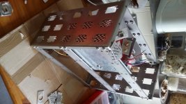
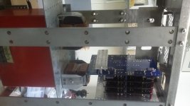
Months ago I did start with construction of the dddac mainframe. I want it to be sturdy because there is some heavy iron inside. I don't want it to twist no matter how I hold or put it after all there are circuit boards inside that don't like to be twisted.
The two sides have rectangular holes that are closed by mounting small plates with threaded holes ( so much easier to install) . When no function is needed they just serve for airflow. Other can serve for mounting cinch, bnc 75 ohm input ( my present dac uses bnc in), power connector, you name it and within a few days it can be changed. No need to start drilling in your precious dac.
Wanna make it in such a way that it can function like pictured. There will be no connections to other gear on the back side.
Have to find a way to make a nice look at the front side. Not sure if I need these led. Maybe just the input switch.
My 4 board dddac will have the boards mounted vertically to have better airflow and shorter connections.
At first will be used with cd transport. Later other boards can be added for .....things all new to me. Haven't got a clue to be honest.
After reading the old thread I wanted to start a new one because there will be new questions and probably new ideas too.
In the old thread some people start talking about changing the wima caps in the digital part by 100nF kemet PPS caps and the 10microfarad cap by a Sanyo os con.
Some other member did ask Doede and this info was forwarded to me.
C6 and C15 are the most import ones. C11 and C 12 Doede wouldn't care and if then only C12. The kemets are not expensive so not a big dilemma.
On the main board there is a bigger number of 100nF but still not a big investment.
Months ago I did start with construction of the dddac mainframe. I want it to be sturdy because there is some heavy iron inside. I don't want it to twist no matter how I hold or put it after all there are circuit boards inside that don't like to be twisted.
The two sides have rectangular holes that are closed by mounting small plates with threaded holes ( so much easier to install) . When no function is needed they just serve for airflow. Other can serve for mounting cinch, bnc 75 ohm input ( my present dac uses bnc in), power connector, you name it and within a few days it can be changed. No need to start drilling in your precious dac.
Wanna make it in such a way that it can function like pictured. There will be no connections to other gear on the back side.
Have to find a way to make a nice look at the front side. Not sure if I need these led. Maybe just the input switch.
My 4 board dddac will have the boards mounted vertically to have better airflow and shorter connections.
At first will be used with cd transport. Later other boards can be added for .....things all new to me. Haven't got a clue to be honest.
Attachments
Hello,
I thought that the Silmic 10uf 25 volts caps looked small compared to the ones used on the old board ( nich muse KZ 47mF 25 volts). The caps provided in the kit are according to the value indicated in the new updated board so 10 uF but they are 100 volts.
Pin spacing on my Silmic is a bit smaller than de 10 uf muse but they can be used. Maybe dont push them all the way down to the board and/or use a plier to get some extra distance between the pins.
Just have a few Black gate 100uF 16 volts if i wanted to use where would they be benificial?
Greetings, Eduard
Imagine how good things could be if you devoted half a much time to the really important areas of the circuit, like clock distribution, as you do to the choice of 100nf bypass capacitors.
Hello,
Did so some metal work in order to mount the boards. I remember someone asking about the nylon washers included in the new updated kit.
When your soldering height is just a bit higher than average you might need the extra heigth of the washer to prevent the cut of wires touching the same cap on the board underneath.
Usually i will solder and after that cut the excess wire maybe you should cut them before soldering. Once there is solder it is rather difficult to cut the wires REALLY short.
This is tricky business.
Greetings, Eduard
Hello,
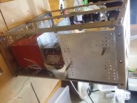
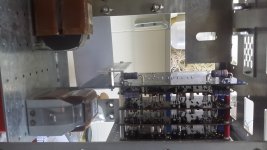
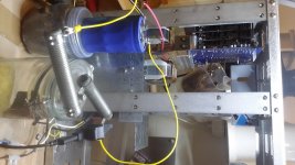
Did make some extra metalwork to mount the circuits in my mainframe.
Not sure if I will use the led part of the mother board anyway I will have to move it to the front panel to be useful.
Did make a metal plate with the pattern for mounting the motherboard or the little board and did copy and paste ( long live cad/cam manufacturing)that pattern on that plate so the position of the board can be moved around.
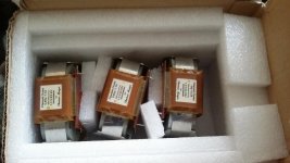
Don't know where I will put the Sowters, probably on the side using the hole pattern also used for the cover plates of the rectangular holes. If the wires are about 20 centimeters I can use the 2 supports I already made. If they are not must make another support . We will see.
Greetings, eduard
Did make some extra metalwork to mount the circuits in my mainframe.
Not sure if I will use the led part of the mother board anyway I will have to move it to the front panel to be useful.
Did make a metal plate with the pattern for mounting the motherboard or the little board and did copy and paste ( long live cad/cam manufacturing)that pattern on that plate so the position of the board can be moved around.
Don't know where I will put the Sowters, probably on the side using the hole pattern also used for the cover plates of the rectangular holes. If the wires are about 20 centimeters I can use the 2 supports I already made. If they are not must make another support . We will see.
Greetings, eduard
Attachments
Hello,
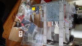
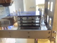
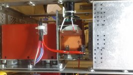
Did put most of the parts on the circuit. Things fit well into the mainframe.
Made a small piece of aluminium attached with the holes originally intended for mounting the motherboard in a chassis. This aluminium piece can support one or two caps so they will be really close to the 12 volt input.
The LCLC power supply will be were the chokes are now.
Chokes and circuit boards can be moved around because I did "" copy and paste "" their mounting pattern.
The piece of metal with the 2 oval holes is used to mount the Sowter outputs from Doede. This piece is mounted with the same holes as the rectangular plates that cover the holes in the two sides.
If I decide to add extra boards the Sowter mounting panel can be moved further away.
Greetings, Eduard
Attachments
Hello,
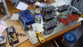
Did start with my boards. Using an old mirror I managed to get from 4 to 8. Greetings, eduard
why do you need two main boards? 🙄
Hello,
Maybe i will put the chassis on a nice bamboo chopping block or get some tropical wood from Vietnam on my next trip.
And i am metal business i am not a carpenter. Wood is for turntables and loudspeakers i guess.
Greetings, Eduard
Maybe i will put the chassis on a nice bamboo chopping block or get some tropical wood from Vietnam on my next trip.
And i am metal business i am not a carpenter. Wood is for turntables and loudspeakers i guess.
Greetings, Eduard
forgot the photos
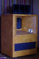
Here are the photos. One is my Sota turntable , the other one is my home made Altec covered with a layer of cork. The horn on top is balsa wood filled with a thin layer of sand. That one had to buy. Even a carpenter like Jesus couldnt make a similar one.
Greetings, Eduard
Here are the photos. One is my Sota turntable , the other one is my home made Altec covered with a layer of cork. The horn on top is balsa wood filled with a thin layer of sand. That one had to buy. Even a carpenter like Jesus couldnt make a similar one.
Greetings, Eduard
Attachments
Hello
Hello,
I did wire the transformer secondary side to the 4 diodes, the first ll2733 , then the first 10000 microfarad then the second ll2733 and then another 10.000 microfarad just for testing the dc voltage. Have to make something to support one or two 10000microfarad who will fit nicely next to the chokes.
Dc output voltage is 13,35 volts but it is midnight here so normally it will a bit lower. Load made with the big resistor is around 820 mA don't expect it to be much lower with the actual load 850 mA.
Could add another ll2733 but wired in parallel which will give an extra .850mA× 0,85 ohm voltage drop. The other two chokes which are not the standard ll2733 but models with a smaller airgap resulting in less current rating but higher inductance ( 700mH and 544 mH )
Greetings, Eduard
Attachments

thanks
Hello,
I did make some stainless steel '' tiptoes '' to lift them up but i never tried because they will probably damage my cork floor because the boxes are sandfilled and weight is above 120 kilo.
Maybe i try if my dddac is finished
Greetings, Eduard
p.s no ideas for my dac????
Hello,
I did make some stainless steel '' tiptoes '' to lift them up but i never tried because they will probably damage my cork floor because the boxes are sandfilled and weight is above 120 kilo.
Maybe i try if my dddac is finished
Greetings, Eduard
p.s no ideas for my dac????
Hello,
Hopely this afternoon will attach the boards outside the chassis to the power supply which is inside. This make checking the voltages and adjusting the 40 mv easier. Let is run for an hour, check again and put it inside the box.
THEN wait for the Sowters to arrive that got lost in transition because two letters failed in the postal code they are making their way back to Germany probably on a bicycle because it takes ages.
Will install the wave IO later because i dont have a power supply yet. Dont know if i will use a shunt supply. Using shunt will restrict the number of chokes that can be used. Without the shunt can use ll1638 which will give 4000mH in differential connection. Using LCLC is not to expensive. Voltages are low so caps can be higher µF .
Dont know if one should look for different properties compared to the 12 volt supply.
My chassis is in a stage that all metal work that still needs to be done is rather simple using my machine at work. Maybe one or two sheets will need a 90 degree bending but that is plain simple with several coworkers and their machines.
Doede told somewhere that he is using an Aurender device with great results so i start reading about it. Looks nice but pretty expensive for a South Korean product. Hope it will not be outdated within a few years because this is a kind of '' computerbased'' gear.
Greetings, Eduard
Hello,
Did add the Belleson regulators on the mainboard. This evening will try to finish the Belleson saupply i did buy for the wave IO
The belleson regulators on the mainboard need a minimum current to work properl;y. So all 3 have a bleeder to assure around 15 mA.
But now the input voltage voltage on the 7810 regulator is just about 1,1 volt higher than the output. Current drawn is around 100mA so i think difference between in and output voltage could be lower?
If not i will change the hexfreds to scottkys to have an extra? volt?
greetings, eduard
Hello,
Did install some ordinary schottky diodes and now input voltage is what it should be.
With the help of Doede and Brian from belleson corporation i did get some ideas how to get the 3 regulators on the mainboard even better.
Now ''waiting '' for an answer about where to connect the negative pole of the additional LC network used for each regulator.
If i put the cap right at the input of the regulator where to connect its negative pole to the negative pole of the cap mounted at the output of the regulator or use a wire to connect it to the negative pole of big cap next to the 12 volt terminal block?
Greetings, Eduard
p.s will post results later after getting input here

- Status
- Not open for further replies.
- Home
- Source & Line
- Digital Line Level
- Adventures in dddac land