Hi there.
I've been studying horn reflex designs for some time now and have built a number of my own design, only one of which I am happy with and that produces the boosted characteristics over a direct radiating approach (more SPL, good low frequency extension etc)
I put horn reflex in the title to include the sort of thing, for example, Martin Audio make and also the 'tapped horn' a la Danley Sound Labs (wherein the driver is reversed).
The failed cabinets I've built have typically been too small, that's the main problem.
I've been looking carefully at Danley's home cinema subs- the TH-SPUD for example- and I am puzzled as to how they produce any advantage over direct radiating designs.
I can see the path length is right for getting the 15hz and up response, but the mouth is really small. And relative to the way a 15hz wave would naturally propagate in open air, the pathway is very narrow.
I've tried making cabinets where the mouth is small and the pathway is narrow but long (and thus the geometry of the horn expands very slowly over the length of the horn) and I end up with basically no gain in SPL over direct radiating.
I suppose there is the slow roll off at the bottom corner of the response that is lost when you port a direct radiating cabinet.. That's there.
But why not just build a direct radiator with really low fs and really long ports?
I know that was a bit of an essay, but if anyone has any thoughts, I'd be interested to hear.
Thanks
Peter,
The advantage of properly designed tapped horns or horn/ported designs are from an efficiency standpoint- as much (or even more than) 6dB SPL gain over standard bass reflex designs using the same drivers.
6dB additional gain requires half the drivers and amplification to achieve the same output SPL, but also requires more cabinet volume, and arguably reduced "sound quality" due to the resonant behavior responsible for the gain.
The TH-SPUD 19 Hz – 125 Hz - 3 dB response at 94 dB 1/w 1meter half space (123 dB @800 watt peak) is impressive, but it occupies 13.75 cubic feet using just two 8" drivers.
In a "home cinema" the small (relative to wavelength) room's modal response dominates the subwoofer's output, most would prefer using 3-4 smaller cabinets distributed around for a more even response, rather than a single larger cabinet.
Art
Last edited:
OK, then curious why this particular [well documented] thread subject?
I mean this 'white paper', Art's description, boils down to [box] acoustic efficiency designed with a tap to fill in its inherent 3rd harmonic dip with its pipe TL/horn harmonics damping the driver much better than a BR.
Note too that the Spud's vent pipe end correction is huge relative to a typical BRs, adding further damping.
Can't recall ever calculating it, but the BR would typically need a relatively large false wall baffle around it to match, i.e. for HT apps, either flush in-wall and/or floor mounting or at least false built-in corner/floor subs.
Regardless, as you've already learned empirically, 'bigger is better' [BIB] rules down low regardless of how you get there and the answer to your core question:
.....is at the time of the 'white paper', from dim memory there was only one truly low Fs woofer with [then] high power handling and a high Vas for efficiency with a commensurately high price, so the TH was pretty much a 'no brainer' option if only needing a < ~120 Hz XO point.
Again though, Dr. Geddes' or Dr. Toole's multiple sub system to take advantage of room modes are the best overall choices, making THs mostly moot nowadays in HIFI/HT apps if one can afford the cost/effort.
I mean this 'white paper', Art's description, boils down to [box] acoustic efficiency designed with a tap to fill in its inherent 3rd harmonic dip with its pipe TL/horn harmonics damping the driver much better than a BR.
Note too that the Spud's vent pipe end correction is huge relative to a typical BRs, adding further damping.
Can't recall ever calculating it, but the BR would typically need a relatively large false wall baffle around it to match, i.e. for HT apps, either flush in-wall and/or floor mounting or at least false built-in corner/floor subs.
Regardless, as you've already learned empirically, 'bigger is better' [BIB] rules down low regardless of how you get there and the answer to your core question:
But why not just build a direct radiator with really low fs and really long ports?
.....is at the time of the 'white paper', from dim memory there was only one truly low Fs woofer with [then] high power handling and a high Vas for efficiency with a commensurately high price, so the TH was pretty much a 'no brainer' option if only needing a < ~120 Hz XO point.
Again though, Dr. Geddes' or Dr. Toole's multiple sub system to take advantage of room modes are the best overall choices, making THs mostly moot nowadays in HIFI/HT apps if one can afford the cost/effort.
GM,Can't recall ever calculating it, but the BR would typically need a relatively large false wall baffle around it to match, i.e. for HT apps, either flush in-wall and/or floor mounting or at least false built-in corner/floor subs.
.....is at the time of the 'white paper', from dim memory there was only one truly low Fs woofer with [then] high power handling and a high Vas for efficiency with a commensurately high price, so the TH was pretty much a 'no brainer' option if only needing a < ~120 Hz XO point.
At < ~120 Hz, there would be no more "need" for a a relatively large false wall baffle around a BR compared to a TH or FLH.
Regarding the time of the DSL "white paper", it's release was around the time Tom formed Danley Sound Labs (after Intersonics and Sound Physics Labs) in 2005. By then, the LAB 12 and many other low Fs/high Xmax woofers were readily available, and amplifier power cost per watt had been steadily dropping for over 3 decades.
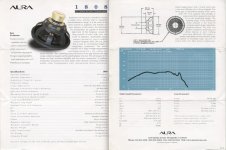
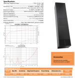
You may remember the specification sheet from 2/1997 for the Aura 1808, it's "unique motor structure that is completely unconventional in design" was an example of one truly low Fs woofer with [then] high power handling and a high Vas for efficiency with a commensurately high price.
Anyway, the longer we are around, the more history keeps repeating itself..
Art
Attachments
Well, I was particularly incredulous about the performance of the th-spud.
But I think I’ve grasped why it works despite its mouth size.
But I think I’ve grasped why it works despite its mouth size.
OK, then curious why this particular [well documented] thread subject?
I mean this 'white paper', Art's description, boils down to [box] acoustic efficiency designed with a tap to fill in its inherent 3rd harmonic dip with its pipe TL/horn harmonics damping the driver much better than a BR.
Note too that the Spud's vent pipe end correction is huge relative to a typical BRs, adding further damping.
Can't recall ever calculating it, but the BR would typically need a relatively large false wall baffle around it to match, i.e. for HT apps, either flush in-wall and/or floor mounting or at least false built-in corner/floor subs.
Regardless, as you've already learned empirically, 'bigger is better' [BIB] rules down low regardless of how you get there and the answer to your core question:
.....is at the time of the 'white paper', from dim memory there was only one truly low Fs woofer with [then] high power handling and a high Vas for efficiency with a commensurately high price, so the TH was pretty much a 'no brainer' option if only needing a < ~120 Hz XO point.
Again though, Dr. Geddes' or Dr. Toole's multiple sub system to take advantage of room modes are the best overall choices, making THs mostly moot nowadays in HIFI/HT apps if one can afford the cost/effort.
For something a bit more detailed then (to make use of the thread)...
What I cannot account for is why the Danley sub’s response (for example the TH-115) continues to rise smoothly (albeit with one jump) between about 80hz and 150hz.
I’ve modelled the same drivers used in Danleys designs in Hornresp and it comes up with a lump a bit above the turning frequency, then a lump at about 100hz, then a massive spike at about 140.
I’ve tried every combination of box size and path length.
And indeed with the model I’ve made, it responds roughly how Horresp thinks.
I can’t see from looking at the B&C drivers responses that there is any increase in response in this region that would account for this phenomenon.
Thank you
Peter
OK, then curious why this particular [well documented] thread subject?
I mean this 'white paper', Art's description, boils down to [box] acoustic efficiency designed with a tap to fill in its inherent 3rd harmonic dip with its pipe TL/horn harmonics damping the driver much better than a BR.
Note too that the Spud's vent pipe end correction is huge relative to a typical BRs, adding further damping.
Can't recall ever calculating it, but the BR would typically need a relatively large false wall baffle around it to match, i.e. for HT apps, either flush in-wall and/or floor mounting or at least false built-in corner/floor subs.
Regardless, as you've already learned empirically, 'bigger is better' [BIB] rules down low regardless of how you get there and the answer to your core question:
.....is at the time of the 'white paper', from dim memory there was only one truly low Fs woofer with [then] high power handling and a high Vas for efficiency with a commensurately high price, so the TH was pretty much a 'no brainer' option if only needing a < ~120 Hz XO point.
Again though, Dr. Geddes' or Dr. Toole's multiple sub system to take advantage of room modes are the best overall choices, making THs mostly moot nowadays in HIFI/HT apps if one can afford the cost/effort.
Peter,What I cannot account for is why the Danley sub’s response (for example the TH-115) continues to rise smoothly (albeit with one jump) between about 80hz and 150hz.
I’ve modelled the same drivers used in Danleys designs in Hornresp and it comes up with a lump a bit above the turning frequency, then a lump at about 100hz, then a massive spike at about 140.
I’ve tried every combination of box size and path length.
In addition to box size and path length, the relative distance relationships between the two "taps" and the mouth exit are critical to achieving the desired frequency response over the pass band, without nulls and peaks.
You might be interested in the Keystone sub, developed 10 years ago, it's frequency and phase response closely match the DSL TH-115/TH-118.
Tapped Horn Vs. Bass Reflex Case Study
Art
Very interesting (the keystone).
Very briefly - I read somewhere that Tom has said it's best to use a tuning slightly below the driver's Fs (ie the distance between the entry and the tap being slightly longer than 1/4 wavelength at that Fs).
Is this something with which you agree?
Thanks for your thoughts.
Peter
Very briefly - I read somewhere that Tom has said it's best to use a tuning slightly below the driver's Fs (ie the distance between the entry and the tap being slightly longer than 1/4 wavelength at that Fs).
Is this something with which you agree?
Thanks for your thoughts.
Peter
For something a bit more detailed then (to make use of the thread)...
What I cannot account for is why the Danley sub’s response (for example the TH-115) continues to rise smoothly (albeit with one jump) between about 80hz and 150hz.
I’ve modelled the same drivers used in Danleys designs in Hornresp and it comes up with a lump a bit above the turning frequency, then a lump at about 100hz, then a massive spike at about 140.
I’ve tried every combination of box size and path length.
And indeed with the model I’ve made, it responds roughly how Horresp thinks.
I can’t see from looking at the B&C drivers responses that there is any increase in response in this region that would account for this phenomenon.
Thank you
Peter
The thing you might be missing is this: the Danley tapped horns have other things going on, which means they can be smoother towards the top of the frequency band.
IIRC, there's a couple of 1/4-wave resonators (in the form of PVC pipes, open at one end and stuffed) which absorb some output (in a tuned frequency range, towards the top of the bandwidth) from the horn-side of the cone. That would leave only the mouth-side of the cone radiating at the upper range, so the frequency response can be smoother.
It's a neat idea, but I'm not sure if Hornresp can model such things.
Chris
Originally Posted by peterjohnswindley post #10
"Very briefly - I read somewhere that Tom has said it's best to use a tuning slightly below the driver's Fs (ie the distance between the entry and the tap being slightly longer than 1/4 wavelength at that Fs)."
DSL builds tapped horns with the lower impedance/excursion minima "tuning" both near, above or below the driver's Fs, so what's "best" depends on the application.
The driver used in the DSL TH-118 and TH-118XL is the B&C18SW115-4 with an Fs of 34Hz.
The TH-118 impedance/excursion minima is about 35Hz (the Keystone's 37Hz) while the TH-118XL is around 30Hz.
I'm fairly sure the driver used in the TH-Mini has an Fs of 42Hz, while it's impedance/excursion minima is at around 50 Hz, while the TH-221 goes the other direction, Fs 30Hz, impedance/excursion minima in the 20Hz region.
Last edited:
Chris,IIRC, there's a couple of 1/4-wave resonators (in the form of PVC pipes, open at one end and stuffed) which absorb some output (in a tuned frequency range, towards the top of the bandwidth) from the horn-side of the cone.
Danley does use absorbers in some of his TH designs, but not in any so far discussed in this thread.
Art
The thing you might be missing is this: the Danley tapped horns have other things going on, which means they can be smoother towards the top of the frequency band.
IIRC, there's a couple of 1/4-wave resonators (in the form of PVC pipes, open at one end and stuffed) which absorb some output (in a tuned frequency range, towards the top of the bandwidth) from the horn-side of the cone. That would leave only the mouth-side of the cone radiating at the upper range, so the frequency response can be smoother.
It's a neat idea, but I'm not sure if Hornresp can model such things.
Chris
Ah!
Interesting.
Not sure I quite understand where these pipes are located?
To further illustrate what I'm getting at - I've attached (hopefully...) an image. I've stretched the horn resp window such that it matches the scale of the Danley plot (TH-115).
Every Horn resp plot I've seen is similar to mine here; three lumps. One around the tuning frequency, one a bit further up, and then one big jump between about 110 and 150hz.
Whereas the danley graph shows a much more even rising response.
Attachments

At < ~120 Hz, there would be no more "need" for a a relatively large false wall baffle around a BR compared to a TH or FLH.
Regarding the time of the DSL "white paper"
You may remember the specification sheet from 2/1997 for the Aura 1808
Anyway, the longer we are around, the more history keeps repeating itself.
Greets!
Relative to the SPUD, a typical sub cab won't have anywhere near the vent's acoustic boundary area, hence the need for a baffle to match even at 120 Hz if in the same location, so for HT apps big enough to warrant such a sub system, false wall/builtin installs is IME from doing big FP systems in relatively small rooms an easy way to integrate them.
Actually, I obviously didn't/don't remember, thinking it was a bit earlier as I had it in my head it was around '98 when Tom tweaked my curiosity WRT a new invention in a PM and at the time I posted I could only remember the McCauley 6174 in that period with the Aura a bit later.
Regardless, with increasingly failing memory since '14 highlighted by yours and another's similar post on another thread, it's depressingly obvious I'll have to 'refresh' my memory before posting from now on or stick to Qs that I have quick reference to if need be as my quality/hobby time has been shrinking even quicker nowadays than my memory. 🙁
Indeed!
IIRC, there's a couple of 1/4-wave resonators (in the form of PVC pipes, open at one end and stuffed) which absorb some output (in a tuned frequency range, towards the top of the bandwidth)
Right, band-stop filters though only familiar with them being in the DTS 20: http://users.cms.caltech.edu/~ps/All.pdf
Can't find the pictures of them installed in a quick search. 🙁
Not sure I quite understand where these pipes are located?
Every Horn resp plot I've seen is similar to mine here; three lumps. One around the tuning frequency, one a bit further up, and then one big jump between about 110 and 150hz.
Whereas the danley graph shows a much more even rising response.
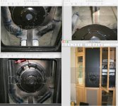
The PVC pipe tuned absorbers used in the DSL DTS20 are located near the mouth, IIRC, been over 10 years since we've seen them, may have been one on either side of the driver. As GM posted, can't find the pictures of them anymore.
The center arrangement of the driver in the 87.5" tall cabinet caused a "pipe resonance" peak around 160 Hz, the absorbers reduced that out of band peak, leaving a tell-tale smaller dual impedance peak in that region.
The upper peak was not eliminated entirely, though the marketing frequency response graph ending at 100Hz does ;^).
DSL no longer has the DTS20 listed in their products, none of the other current TH are arranged such that the narrow band problem the DTS20 had occur so near to the sub's passband.
Regarding the "more even rising response" in an actual TH than in your Hornresp simulation, some of the difference is due to the smoothing used in measurements, some is due to the simulation not reflecting the actual "as built" horn (or driver used), and some is due to the simulation showing theoretical peaks that are damped by both driver and cabinet response.
At any rate, the differences you posted are only a few dB, in room response can vary far more than that in a few feet, so nothing to get excited about.
Art
Attachments
Last edited:
Finally found them; what 'bugs' me though is I've posted them here, yet can't find them regardless of how I search for them 🙁: which is better, epik conquest or danley dts-20 - Page 2 — Polk Audio Forum
GM, good find- the DTS 20 absorbers appear to be both pointed up to the top of the cabinet, the left pipe is shorter, the right is labeled "31 3/4", probably it's length in inches.
Wonder if the builder had a plumbing license, plenty of glue left on the driver ;^)
Forgot about the series coil and foam lining, very fiddly compared to DSLs more recent designs.
Wonder if the builder had a plumbing license, plenty of glue left on the driver ;^)
Forgot about the series coil and foam lining, very fiddly compared to DSLs more recent designs.
Attachments
The series inductance can help to both boost and smooth the response in the passband.
Of course, using a driver with suitable inductance to begin with addresses those issues as well.
Of course, using a driver with suitable inductance to begin with addresses those issues as well.
- Home
- Loudspeakers
- Subwoofers
- Advantage of a horn reflex sub for home cinema??