Hello,
after having searched through various resources for a nice LR filter design online i've started to make my own schematic and PCB - as i'm still a beginner i've tried to keep close to what i've found. My goal is a LR-Filter that can nicely be adjusted by plugging four precision resistors mounted on a IC socket into another IC socket. After having finished the PCB design i had the idea to simulate my schematic to save the hassle of building a prototype that most probably wouldn't work yet ;P. So i read a little into ltspice (which seemed quite useable from what i heared) and tried:
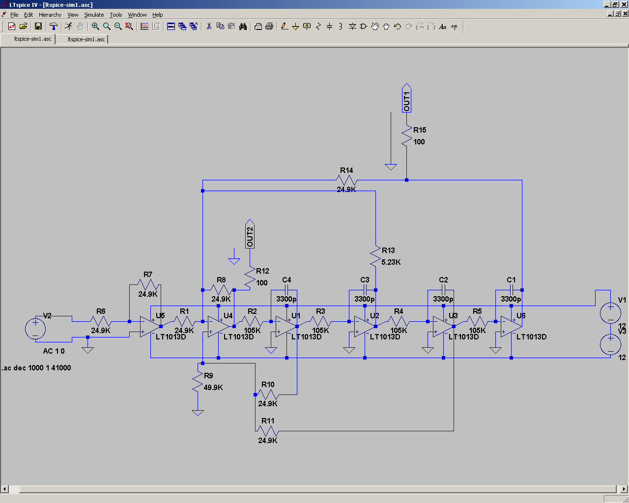
then i clicked simulate, picked my two outputs and BAAAM:
Nope ... thats not what a good crossover should look like. Maybe for some magic strange usecase, but certainly not for audio.
As a friend i asked presented me with a working LR SPICE model i'm not totally out of options here, however ... i'd really like to understand what the hell is going on here and why this isn't working? Also, i'd be nice if i wouldn't have to re-do the PCB 😛. By the way: the PCB is designed to be home-etchable and... well, if someones interested to have a look, it's here:
ActiveCrossOver - Adjustable active 24db LR crossover
Thanks in advance - and best regards!
- NebuK
after having searched through various resources for a nice LR filter design online i've started to make my own schematic and PCB - as i'm still a beginner i've tried to keep close to what i've found. My goal is a LR-Filter that can nicely be adjusted by plugging four precision resistors mounted on a IC socket into another IC socket. After having finished the PCB design i had the idea to simulate my schematic to save the hassle of building a prototype that most probably wouldn't work yet ;P. So i read a little into ltspice (which seemed quite useable from what i heared) and tried:
then i clicked simulate, picked my two outputs and BAAAM:
Nope ... thats not what a good crossover should look like. Maybe for some magic strange usecase, but certainly not for audio.
As a friend i asked presented me with a working LR SPICE model i'm not totally out of options here, however ... i'd really like to understand what the hell is going on here and why this isn't working? Also, i'd be nice if i wouldn't have to re-do the PCB 😛. By the way: the PCB is designed to be home-etchable and... well, if someones interested to have a look, it's here:
ActiveCrossOver - Adjustable active 24db LR crossover
Thanks in advance - and best regards!
- NebuK
Are you trying to make second order (12dB/oct) or fourth order (24dB/oct) filters?
That circuit doesn't resemble any kind of filter I've seen before. Where did you find the design? Links to anything similar?
That circuit doesn't resemble any kind of filter I've seen before. Where did you find the design? Links to anything similar?
Heyyas,
i've seen the circuit in
http://www.rane.com/pdf/linriley.pdf
as a abstract concept. Later, i've found another reference in the manual of some product not available in europe, its:
http://www.marchandelec.com/ftp/xm1man.pdf
I was under them impression that what i schematic'ed was a 24db/oct L-R filter... :/
Thanks so far! 😛
OK, I simulated the circuit and got reasonable results. Maybe LTSpice got it's panties in a twist because you didn't put a ground connection at the midpoint of your power supply between V1 and V3. I've been caught like that before, but wouldn't have thought it would make a difference with opamps.
In my simulation, the phase response of the high-pass and low pass are identical (good), but the amplitudes cross at -9dB (bad, should be -6dB).
It looks like you copied the circuit from the second link. I notice the resistor ratios are different to what's recommended in the first link. Maybe if you change to those ratios, you'll get the correct response, crossing over at -6dB.
p.s. Nice filter design! Thanks for sharing.🙂
Attachments
Mh, i was trying to get my model working in ltspice first ... i've tried both, connecting the ground between my voltage sources as well as using a (ideal) opamp model without supply voltage connections ... both resulted in strange and even stranger plots. I'm still totally at loss at whats going on here. Haven't tried the resistor ratios yet since i wanted to get the rest sorted out first.
As for the filter design itself, i was planning to use this for a flexible, modular crossover and subwoof equalisation system. So i could easy and cost-effectively activate any speaker designs as well as use it as a standalone subwoofer eq (in conjunction with a appropriate amp)... Once this works (and maybe i'll have a bunch of questions more, be warned ;P) i wanted to make a nice pcb design so everyone could use it (if it doesn't suck badly ... i'm still a beginner, so ... ;P).
Thanks a bunch! Regards
- NebuK
Which resistors are changed to change the filter frequency?
The seven 24k9, or the one 5k23, or the four 105k?
Or all 12?
Why does Godfrey's show eight 24k9 resistors?
The seven 24k9, or the one 5k23, or the four 105k?
Or all 12?
Why does Godfrey's show eight 24k9 resistors?
Hey,
uh, unless i'm blind Godfreys design shows 5 (not eight) 24.9K resistors. Its 5 and not 6 because i believe be left out the input buffer(?) opamp - thats why he has only 5 opamps as opposed to my 6(??), right?
Anyways, i was under the impression that the four 105K resistors would need changing for adjusting the crossover frequency.
Thanks, Regards
- NebuK
PS: Just tinkered with leaving out the input buffer opamp just as godfrey did, now my curve looks a little better, with the crossover point at -8.8db / 459hZ... but the low-pass starts rising at ~18k again. It decreases until ~18k / -122db, then rises at a not quite so fast slope... i'm even more confused now?!
49k9 should be two 24k9 connected in series giving 49k8
There's 100r error there.
A four gang resistive adjuster to change the frequency. Can you get sufficiently accurate tracking of the four resistive elements to maintain your 4pole LR characteristic?
There's 100r error there.
A four gang resistive adjuster to change the frequency. Can you get sufficiently accurate tracking of the four resistive elements to maintain your 4pole LR characteristic?
Hey,
i've corrected the 49K9 to 49K8, sadly the rise at ~18k in the lowpass curve didn't vanish :/. I'm now toying around empirically since my understanding of how this circuit works stops there ...
As for the resistive adjustment, i planned to get a set of resistors and use ic sockets to plug the resistors. So i only get a stepped adjustable system, but better than nothing! If this works and proves nice, i thought about either a digital pot (maxim has a few nice ones i think) or resistor banks and switches just as rane proposes...
Thanks once again... 😛 Regards
-NebuK
Also, very strange: I've just tried to copy godfreys circuit 1:1 in ltspice using the ideal opamp (opamp.sub with .lib opamp.sub)... all i get at *any* point in the circuit is a linear frequency response Oo
*EDIT: Okay, that was ******** just now ... and i've found my mistake. Some of my plots hat autoranged mangnitude axis with so many ticks that i wouldn't see the bottom is -500 or something dB - which left me under the impression that my filter was not steep enough ... now i'm going to niceify everything. SOLVED 😛 Yay, thanks so far! 🙂 (but the strange hump in my original schematics lowpass remains 🙁)
*EDIT: Okay, that was ******** just now ... and i've found my mistake. Some of my plots hat autoranged mangnitude axis with so many ticks that i wouldn't see the bottom is -500 or something dB - which left me under the impression that my filter was not steep enough ... now i'm going to niceify everything. SOLVED 😛 Yay, thanks so far! 🙂 (but the strange hump in my original schematics lowpass remains 🙁)
Last edited:
Hi NebuK
It sounds like it worked fine as soon as soon as you left out the input buffer opamp. I've no idea why, because that shouldn't make any difference at all.
Firstly the "bad behavior" at -120dB above 18KHz: That really is a very, very small amount of crosstalk. -120 dB = 0.0001% = 1 part per million. That's far lower than the theoretical minimum possible noise from a CD. It's also less than either the crosstalk, noise, or distortion of most amplifiers.
When you actually build the circuit, the crosstalk will probably be worse than that due to stray capacitance, coupling through the ground wiring and power supply rails etc.
Secondly, the resistor values: As Andrew pointed out, if you use two 24k9 resistors in series instead of 49.9, there is an error of 100 ohms. So what? If you're using 1% tolerance parts, the value could be out by up to 500 ohms anyway.
IMHO, the resistor selection in that circuit is idiotic. The actual values aren't important, it's the ratio between them that counts, so there's no reason to use non-standard or hard-to find values throughout.
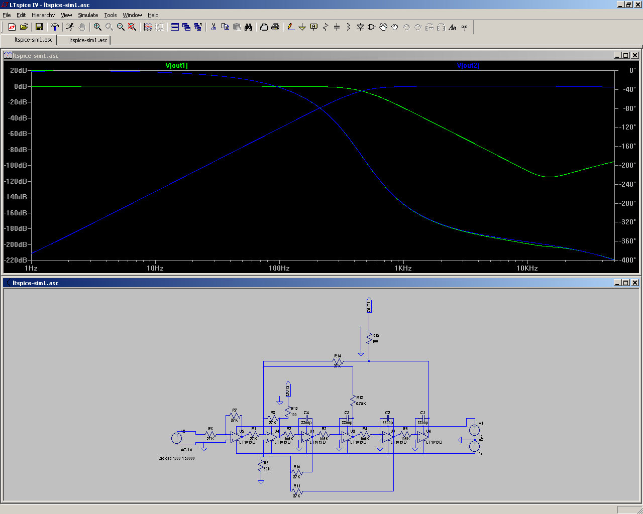
For example, I got the almost perfect results below as follows:
A) Replace all the 24.9K resistors with 27K.
B) Replace the 49.9K resistor with 56K.
C) Replace the 5.23K resistor with 6.75K.
The only non-standard value there is 6.75K, but that's the resistor that needs to be adjustable, so you could use e.g. 4.7K in series with a 5K trimmer, or 5.6K in series with a 2K trimmer, depending on how much adjustment range you want.
Cheers - Godfrey
Edit:
It sounds like it worked fine as soon as soon as you left out the input buffer opamp. I've no idea why, because that shouldn't make any difference at all.
I think you're needlessly worrying here. Let's get a couple of things in perspective.i've corrected the 49K9 to 49K8, sadly the rise at ~18k in the lowpass curve didn't vanish
Firstly the "bad behavior" at -120dB above 18KHz: That really is a very, very small amount of crosstalk. -120 dB = 0.0001% = 1 part per million. That's far lower than the theoretical minimum possible noise from a CD. It's also less than either the crosstalk, noise, or distortion of most amplifiers.
When you actually build the circuit, the crosstalk will probably be worse than that due to stray capacitance, coupling through the ground wiring and power supply rails etc.
Secondly, the resistor values: As Andrew pointed out, if you use two 24k9 resistors in series instead of 49.9, there is an error of 100 ohms. So what? If you're using 1% tolerance parts, the value could be out by up to 500 ohms anyway.
IMHO, the resistor selection in that circuit is idiotic. The actual values aren't important, it's the ratio between them that counts, so there's no reason to use non-standard or hard-to find values throughout.
For example, I got the almost perfect results below as follows:
A) Replace all the 24.9K resistors with 27K.
B) Replace the 49.9K resistor with 56K.
C) Replace the 5.23K resistor with 6.75K.
The only non-standard value there is 6.75K, but that's the resistor that needs to be adjustable, so you could use e.g. 4.7K in series with a 5K trimmer, or 5.6K in series with a 2K trimmer, depending on how much adjustment range you want.
Cheers - Godfrey
Edit:
That's probably just due to the simulator taking into account that real opamps don't have infinite gain and their output impedance isn't zero. Nothing to worry about. As mentioned above, real life will be worse.😉(but the strange hump in my original schematics lowpass remains 🙁)
Attachments

Last edited:
But I would select resistors to better than 0.2% total difference for a single channel. And probably try to get the second channel within that same <0.2% total difference.If you're using 1% tolerance parts, the value could be out by up to 500 ohms anyway.
Fair enough. I wonder how sensitive it is to component tolerance. (I've just managed to talk myself out of wasting an hour of my life trying to find out.😀)
Hey,
i've tried to resimulate a bit, toy around here, toy around there, change the resistors to worst-case-5%-values ... everything still looked okay. Except that strange hump ;P.
Once again, i'll post the picture:
This is now using godfreys values for the resistors. LTSpice has been told the resistors are 5% tolerance parts (i dunno how it takes this into account because ... nothing changed - same with manually adding 5% tolerance btw! I still planned on 0.1% resistors). Well, Even though you tell me there will be higher crosstalk in the real circuit (probably...!), this hump somehow worries me. At 100kHz its at some -87dB, while that is well more silent and high than what we do hear, wouldn't it be better just to get this stuff out as much as possible, as to save the amplifier having to amplify some senseless ghost frequencies?
Thanks a bunch! I'll update my schematic and PCB later and post them for further critique ;P. Thanks so much!
- NebuK
*EDIT: Ps: Capacitor tolerance values seem to be much much worse! I can't seem to find 3.3n caps at under 5% tolerance... but simulating this doesn't - once again - show any difference. So ... i'm on the safe side? (Still trying to get best matched parts possible...)
Last edited:
Hi,
the topology was afaik introduced by Prof. Hawksford in a AES paper "M. 0. J. Hawksford, A family of circuit topologies for the Linkwitz-Riley (LR-4) crossover alignment, Audio Engineering Society preprint No. 2468 (82. Convention, 1987)
In 1995 the german magazine Elrad published a 2-way LS-project featuring a Xover using this schematics.
On demand I could mail both, the Hawksford and the Elektor article.
The basic idea behind this topology is to create a family of subtracting filters, where HP and LP follow each other with great precision.
This special topology allows for lowest component number count of the frequency decicive -low tolerance, high-cost- parts.
Mathematically they exploit the fact with filters of even order (2nd, 4th, etc.) the denominator of the transfer functions of Highpass and Lowpass are the same. The TFs only differ in the numerator.
The Lowpass function may be realized by an equal number of integrations (2x, 4x, etcx) of the Highpass function. This is why we find 2, 4 , etc. integrators in this topology.
(In Nebuks schem these are U1, U2, U3 and U6 together with the RC Networks R2/C4, R3/C3, R4/C2 and R5/C1).
Each integrator can be calculated after the RxC formula. This allows to optimize the R and C values for lownoise or after component tolerance.
As such the requirement for tight component tolerance is relaxed.
The RC-time constants (T=RxC) need to be of distinct (and mostly different) values to achieve the desired character, say B4, LR4, Bessel4, etc.
The output signals of the inverting integrators are summed up (U4, R1, R8-R15, beware of the inversion of the signal from each integrator) and at the same the difference of Input signal and summed-up integrator-signals is formed with U4. All other resistors are just used for gain settings and correct summation of signals. As such all these resistors may be of equal value, say 10kOhm-27kOhm. U5 is just a inverting Input buffer stage and not needed if the source has a low-impedance output.
Compare: A 2nd order Hawksford-Riley-Filter
This is a 2nd order filter which may be expanded to a fourth-order filter by simply adding two integrator stages.
Here, U4 takes up the summing functions of the two integrator signals (U4 is also U4 in Nebuks schematics, so maybe You like to redraw it).
U1 takes the difference of the Input- and the Integrator-signals and forms the HP-output at the same. So the summing and differencing functions are split between U1 and U4. And U1 presents the signal an non-inverting Input.
While the filter worked well at frequencies of a couple of hundreds Hz on, I sometimes got oscillation effects with low crossover-frequnecies.
I finally dropped this filter, because it is an "ideal" filter, if the load is an ideal load like a resistor. It does not take into account the drivers own amplitude and phase-response. To achieve the required acoustic response each driver demands additional equalization, which turns the low part number count advantage of this filter to the opposite (The Elrad article also describes the design of such equalizer-filters) .
I therefore came back to design each filter specially after the requirements of its LS-driver, as it is usual practise with passive filters. This resulted in the end with superior results and lower parts number count.
jauu
Calvin
the topology was afaik introduced by Prof. Hawksford in a AES paper "M. 0. J. Hawksford, A family of circuit topologies for the Linkwitz-Riley (LR-4) crossover alignment, Audio Engineering Society preprint No. 2468 (82. Convention, 1987)
In 1995 the german magazine Elrad published a 2-way LS-project featuring a Xover using this schematics.
On demand I could mail both, the Hawksford and the Elektor article.
The basic idea behind this topology is to create a family of subtracting filters, where HP and LP follow each other with great precision.
This special topology allows for lowest component number count of the frequency decicive -low tolerance, high-cost- parts.
Mathematically they exploit the fact with filters of even order (2nd, 4th, etc.) the denominator of the transfer functions of Highpass and Lowpass are the same. The TFs only differ in the numerator.
The Lowpass function may be realized by an equal number of integrations (2x, 4x, etcx) of the Highpass function. This is why we find 2, 4 , etc. integrators in this topology.
(In Nebuks schem these are U1, U2, U3 and U6 together with the RC Networks R2/C4, R3/C3, R4/C2 and R5/C1).
Each integrator can be calculated after the RxC formula. This allows to optimize the R and C values for lownoise or after component tolerance.
As such the requirement for tight component tolerance is relaxed.
The RC-time constants (T=RxC) need to be of distinct (and mostly different) values to achieve the desired character, say B4, LR4, Bessel4, etc.
The output signals of the inverting integrators are summed up (U4, R1, R8-R15, beware of the inversion of the signal from each integrator) and at the same the difference of Input signal and summed-up integrator-signals is formed with U4. All other resistors are just used for gain settings and correct summation of signals. As such all these resistors may be of equal value, say 10kOhm-27kOhm. U5 is just a inverting Input buffer stage and not needed if the source has a low-impedance output.
Compare: A 2nd order Hawksford-Riley-Filter
An externally hosted image should be here but it was not working when we last tested it.
This is a 2nd order filter which may be expanded to a fourth-order filter by simply adding two integrator stages.
Here, U4 takes up the summing functions of the two integrator signals (U4 is also U4 in Nebuks schematics, so maybe You like to redraw it).
U1 takes the difference of the Input- and the Integrator-signals and forms the HP-output at the same. So the summing and differencing functions are split between U1 and U4. And U1 presents the signal an non-inverting Input.
While the filter worked well at frequencies of a couple of hundreds Hz on, I sometimes got oscillation effects with low crossover-frequnecies.
I finally dropped this filter, because it is an "ideal" filter, if the load is an ideal load like a resistor. It does not take into account the drivers own amplitude and phase-response. To achieve the required acoustic response each driver demands additional equalization, which turns the low part number count advantage of this filter to the opposite (The Elrad article also describes the design of such equalizer-filters) .
I therefore came back to design each filter specially after the requirements of its LS-driver, as it is usual practise with passive filters. This resulted in the end with superior results and lower parts number count.
jauu
Calvin
Last edited:
you, as builder, must do the matching of components where matched components are required by the circuit.Capacitor tolerance values seem to be much much worse! I can't seem to find 3.3n caps at under 5% tolerance
I would aim for <1% on capacitors. Many caps come in 10% tolerance and worse.
Calvin,
the subtractive filters that I have so far looked at, had a subtractive "error" in their operation. They did not give the equal slope in the low pass and high pass sections.
Does the Hawksford implementation overcome this problem?
the subtractive filters that I have so far looked at, had a subtractive "error" in their operation. They did not give the equal slope in the low pass and high pass sections.
Does the Hawksford implementation overcome this problem?
Hi NebuK
I'm not too familiar with LTSpice but I think if you want it to tell you the effects of component tolerance, you have to do a "Monte Carlo" analysis.
I tried changing the values manually. The first pic below shows the effect of increasing the 105K resistors one at a time by 20%. The second pic shows the effect of increasing all the other resistors one at a time by 20%.
It seems like a 20% change in any value can throw the response out by up to about 2dB, so I guess 1% tolerance => up to 0.1dB error, with the errors randomly accumulating. The variable resistor (the 6.75K one) should allow you to tune out the errors fairly effectively.
Re capacitor tolerance:
You can always use a different value of capacitor, and adjust the value of the 105K resistors accordingly. I'd be tempted to increase the capacitance and reduce the resistance, rather than the other way round, to keep the noise down. Having said that, RS components seems to have some suitable caps:
polystyrene capacitor,3300pF 63Vdc 1%
polyprop cap,3.3nF 63V 1%
Re the bump:
All my "pretty" curves were made with "ideal" opamps in the simulation. As soon as I substitute "real" opamps, things look worse. Replacing the opamp on the far right with a LT1013D or TL071 gives me a similar bump to yours. Replacing the opamp second from the right with a LT1013D or TL071 messes up the curves so badly, I think the simulator may be hallucinating.
For best accuracy, I would guess the most important features to look for when choosing the opamp are FET input and high gain.
Cheers - Godfrey
Attachments
Last edited:
low pass active filtering demand adequate opamp performance.
The filter stops filtering if the opamp approaches it's bandwidth limit.
The filter stops filtering if the opamp approaches it's bandwidth limit.
I'm not Calvin, but...Calvin,
the subtractive filters that I have so far looked at, had a subtractive "error" in their operation. They did not give the equal slope in the low pass and high pass sections.
Does the Hawksford implementation overcome this problem?
This type of filter doesn't seem to suffer from that problem. I don't think it's correct to call it a "subtractive" filter (but I also don't want to get into an argument about semantics).
Looking at the outputs from the five opamps gives a good intuitive idea of what's going on. Essentially the output of a 2'nd order high pass filter is passed through four integrators to get the low-pass output.
The only problem is that at very low frequencies the integrators run out of gain, which is probably the cause of the trouble Calvin had.
Attachments
- Status
- Not open for further replies.
- Home
- Source & Line
- Analog Line Level
- Adjustable Linkwitz-Riley filter: Help needed with SPICE