Ok I have done some experimentation with a tube gain stage followed by a cathode follower.
I wanted to see if it's possible to get low distortion and a low output impedance using tubes.
I like tubes as they have a a lot of headroom but the downside is higher distortion and higher output impedance.
After some searching a nice valve for a cathode follower is the ECC88/6DJ8 as the gm is high, rp is on the lower side and it can flow some current. It's nice to have low impedance but it should be able to drive something also....
Afterwards I also noticed the 6C45 which is even better.
So to get low distortion it also meant using extra gain and feedback.
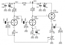
So the schematic I have came up with is this:
So 2 standerd 12ax7/ecc83 gain stages that are capacitor coupled followed by a direct coupled cathode follower using the ECC88.
Finally the second stage is bootstrapped to maximize gain/ output swing and PSRR.
The output is the coupled back to the kathode of the first stage
Gain can be adjusted using the Rgain resistor.
I know the resistor numbers don't start from one, it's just a sketch...
The simulation simmed nice and I also made a test build of this.
Maximum output swing in a 10k load is around 45v rms (that is a little over 120v p-p). And this also was true in the circuit that has been build.
I also simulated a 100k load and that should clip at around 200v p-p. This is possible because of the bootstrapping. the B+ voltage is 300v
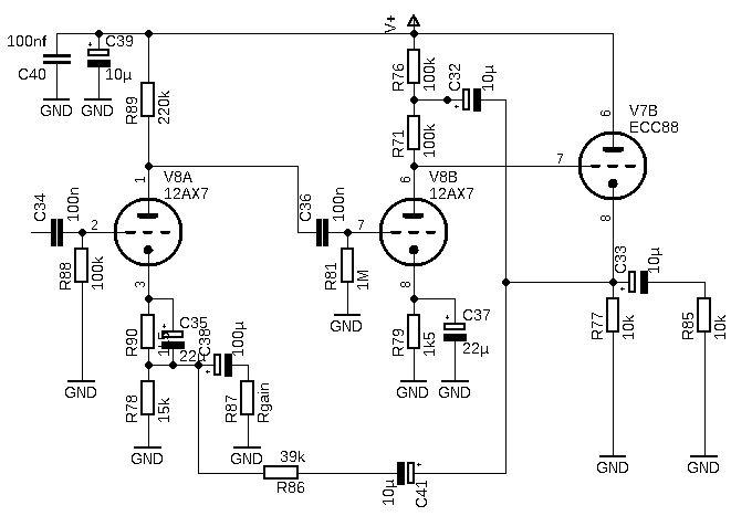
Output impedance is simmed at around 4ohm! (with 12db gain)
If the gain is raised the output impedance also goes up.
With 32db gain the output impedance simmed around 40ohm
I didn't measure the output impedance but changing the load from 1k to nothing didn't change the output voltage much so the output impedance is low.
Distortion is simulated at 0.05% Still have to measure this on the real circuit.
So a few simulation plots.:
Output impedance, I made the output capacitor bigger otherwise the lower frequence goes up and teh scale becomes to big to read.
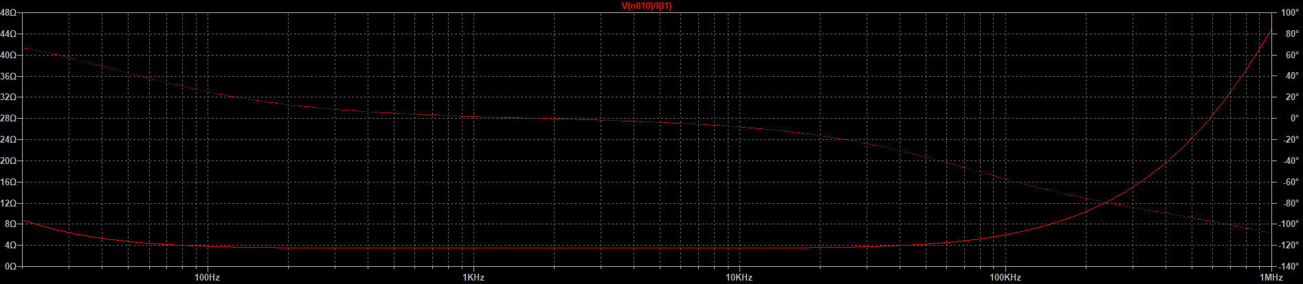
Frequency response around 12db gain
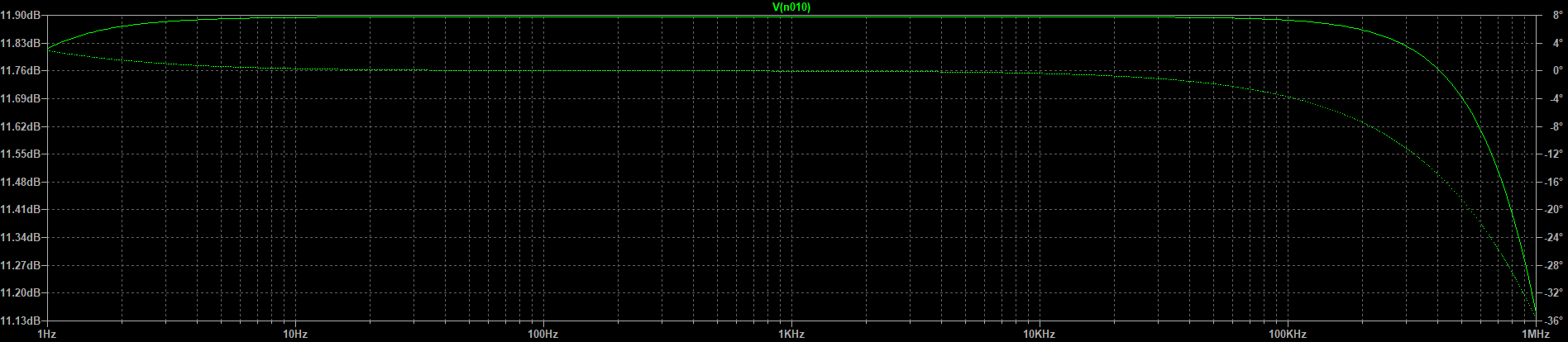
Response at around 32db
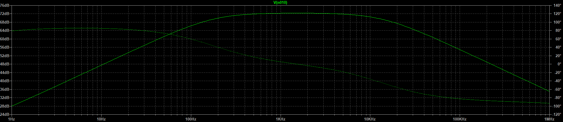
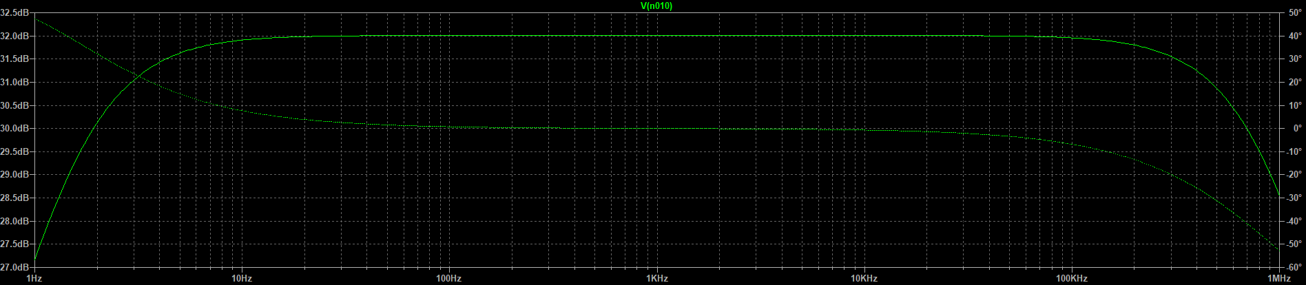
Openloop response.
The lower frequency could be made better using higher value capacitors.
I am planning on using this stage for gains ranging from 12 to 36 db.
I also simmed the 6c45pi as output and I was able to drive a 1k load to 12.5vrms. in 10k the drive increased to 55vrms (160v p-p)
In 100k the drive was a little bit less ( around 180vp-p) then the ecc88 in 100k.
The 6c45 also had a lower output impedance. Especially in the higher frequency's.
I don't have a 6c45 t test this but I think it should work if the circuit is stable. It has a very high gm which is good I think but also prone for oscillation.
So in my conclusion so far I like the bootstrapping principle. It has some of the advantages of an SRPP stage but you don't need "high" voltage to get some decent output swing. Because of the capacitor the midpoint of the two resistors can actually swing higher then the power supply voltage.
Then I know I used a lot of feedback what is normally not done with tubes.
I just like to try something different. Still have to properly set it up and listen to it.....
I wanted to see if it's possible to get low distortion and a low output impedance using tubes.
I like tubes as they have a a lot of headroom but the downside is higher distortion and higher output impedance.
After some searching a nice valve for a cathode follower is the ECC88/6DJ8 as the gm is high, rp is on the lower side and it can flow some current. It's nice to have low impedance but it should be able to drive something also....
Afterwards I also noticed the 6C45 which is even better.
So to get low distortion it also meant using extra gain and feedback.
So the schematic I have came up with is this:
So 2 standerd 12ax7/ecc83 gain stages that are capacitor coupled followed by a direct coupled cathode follower using the ECC88.
Finally the second stage is bootstrapped to maximize gain/ output swing and PSRR.
The output is the coupled back to the kathode of the first stage
Gain can be adjusted using the Rgain resistor.
I know the resistor numbers don't start from one, it's just a sketch...
The simulation simmed nice and I also made a test build of this.
Maximum output swing in a 10k load is around 45v rms (that is a little over 120v p-p). And this also was true in the circuit that has been build.
I also simulated a 100k load and that should clip at around 200v p-p. This is possible because of the bootstrapping. the B+ voltage is 300v
Output impedance is simmed at around 4ohm! (with 12db gain)
If the gain is raised the output impedance also goes up.
With 32db gain the output impedance simmed around 40ohm
I didn't measure the output impedance but changing the load from 1k to nothing didn't change the output voltage much so the output impedance is low.
Distortion is simulated at 0.05% Still have to measure this on the real circuit.
So a few simulation plots.:
Output impedance, I made the output capacitor bigger otherwise the lower frequence goes up and teh scale becomes to big to read.
Frequency response around 12db gain
Response at around 32db
Openloop response.
The lower frequency could be made better using higher value capacitors.
I am planning on using this stage for gains ranging from 12 to 36 db.
I also simmed the 6c45pi as output and I was able to drive a 1k load to 12.5vrms. in 10k the drive increased to 55vrms (160v p-p)
In 100k the drive was a little bit less ( around 180vp-p) then the ecc88 in 100k.
The 6c45 also had a lower output impedance. Especially in the higher frequency's.
I don't have a 6c45 t test this but I think it should work if the circuit is stable. It has a very high gm which is good I think but also prone for oscillation.
So in my conclusion so far I like the bootstrapping principle. It has some of the advantages of an SRPP stage but you don't need "high" voltage to get some decent output swing. Because of the capacitor the midpoint of the two resistors can actually swing higher then the power supply voltage.
Then I know I used a lot of feedback what is normally not done with tubes.
I just like to try something different. Still have to properly set it up and listen to it.....
Last edited:
The cap of 10µF is like a short for AC signals. the bigger the cap the lower the AC signals can be.
Using 10µF the phase is still within limits even at 20Hz.
The resistor of 10k is the actual load
It can probably be smaller for the bootstrap but in real life the circuit was stable and impulse signals looked ok.
Still have to do some more evaluation.
Using 10µF the phase is still within limits even at 20Hz.
The resistor of 10k is the actual load
It can probably be smaller for the bootstrap but in real life the circuit was stable and impulse signals looked ok.
Still have to do some more evaluation.
I was able to drive a 1k load to 12.5vrms
Do you have some special purpose for this circuit, or do you just want to search how "far" you can go with tubes ?
I like the way you left out one capacitor by DC coupling the feedback.
However I did like the bootstrap.
When I put the input resistor on the junction of R78/R90 the circuit becomes unstable at low frequency's. Simulating this also causes a big bump at extreme low frequency's.
In the real circuit this was also true.
Putting this resistor to GND solved this.
Using A DC feedback path can solve this I think
My main goal is to experiment and see how far I can go with tubes. I also like to try different things then what has been done.
On the other hand I was thinking If I would use two of these circuits with around 32db of gain and use a passive RIAA network in between, it could be a nice riaa preamp. I would change the input resistor of the first circuit to 47k then.
For the second circuit I would make it higher to not interfere to much with the riaa network.
As the output impedance is low it wouldn't be of much influence either.
Using one circuit with around 12db of gain could be a nice line amp that can drive most amplifier without problems.
Ok I changed a few things.
I left out some capacitors to DC couple the feedback path. However I like to be able to set gain external with one resistor so couldn't really make more simple.
For practical use I would probably have to AC couple the external resistor otherwise changing gain would make a loud pop.
The input resistor is now tied to the junction of the kathode resistors. Because there is one less capacitor it is more stable now.
I also added the RC ripple reduction to the first stage and this works very nice.
If I simulate this with a gain of 12db and 1V ripple on the supply I get around 0.5mV rms ripple at the output. good for more then 70db of hum reduction from the power supply ....😎
At higher gain this decreases but still not really bad.
The maximum output swing also got up to more then 50vrms in 10k
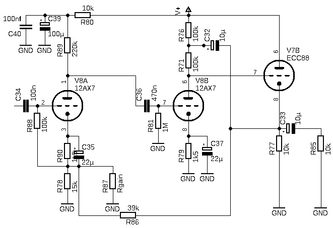
I have actually built circuits like this to test, I used a Russian 6S3P-EV as the first tube and 12AU7 for the last two. Sound was excellent, even though there are 3 capacitors in the signal path, it still outperformed my 6SN7 based zero feedback preamp that only had a single output cap.
I simmed distortion as 0.0015% at 1V out and confirmed with measurement. Interestingly using a ECC99 as the second stage increased THD at 1V but decreased it at higher levels, so there must have been some 2H cancellation going on at low levels.
I simmed distortion as 0.0015% at 1V out and confirmed with measurement. Interestingly using a ECC99 as the second stage increased THD at 1V but decreased it at higher levels, so there must have been some 2H cancellation going on at low levels.
I just noticed that the kathode resistor of the ecc88 should be increased to 22k when using 300v. Otherwise it will be toasted. 6c45pi can cope with a little bit more dissipation and current.
Second thing i've noticed is that I adjusted simulation parameters and the distortion dropped to 0.000087% 😱.
This is with 12db gain and an output of 2.5 Vrms in 10k
Ofcourse this is all fantasy simulation....
Distortion spectrum show mostly 2nd order distortion.
But when you go to the limits it gets more complex
I think I should get me some 6c45pi tubes as they are a lot better then the ecc88.
Simulated distortion drops to 0.000013%
In a few days I think I will have time to measure this in real life with an AP analyzer
Sounds like if you used a differential front end you may be into a nice vacuum state operational amplifier. You would need to do some work to get the same gain from each input, or you could go to a output stage that takes a balanced input.
Why 300V ? I proposed 200V, more isn't needed.I just noticed that the kathode resistor of the ecc88 should be increased to 22k when using 300v. Otherwise it will be toasted.
Give me 100V and 10mA = 1W for the ECC88.
The triode driving the cathode follower has an easy task, very high input impedance, so one can use a high anode resistor.220k is already almost 4x the Zi of the tube, not much to gain from the bootstrapping.
The first half of the ECC83 must drive the miller-C of the next, better keep the Ra lower, there a 100k.
Only bypassing the cathode of the second triode is perhaps not the best place, rather bypass the first triodes cathode (// R90).
Don't forget to protect the grid ofthe cathode follower from high voltages at start-up (diode or ne-bulb).
Mona
Checkout the Philbrick valve opamp specs, 0.2 ohms output impedance closed-loop, 300 ohms open-loop: http://www.philbrickarchive.org/k2-x_refurbished.pdf
I was thinking about something like this could be possible but it would be nice to have balanced in & balanced out.
You can then directly drive some output tubes and if needed into a little bit of grid current.
The input could take a balanced input or unbalanced input.
Still have to figure out the details
You can then directly drive some output tubes and if needed into a little bit of grid current.
The input could take a balanced input or unbalanced input.
Still have to figure out the details
Checkout the Philbrick valve opamp...
I think the quoted value is for "DC"? At the top of the audio band it may be >100r in unity gain.
..if it's possible to get low distortion and a low output impedance using tubes.....
About everything is possible.
For low Zout: a plan I stole from another thread is sure capable of fairly low output impedance. I do NOT know why this is critical in Hi-Fi. (I had an application to drive 4 to 20 recorders in live performance where "any" fault should not cause audible change in the non-faulted feeds, so I needed few-Ohm Zout.) The plan as shown can do 8V at about 4% THD, so around half-% THD at 1V. The amp I had could be strapped to unity gain(!) so under 1/10% THD. (For this gig I did want less than that so I went with a boosted opamp.)
Attachments

- Home
- Amplifiers
- Tubes / Valves
- Adjustable Gain stage experiments (12ax7 +ecc88)