Lumba Ogir said:syn08,
this is an outstanding topology. You could reverse polarity using matched 2SC2457s, manual trimming still will be necessary.
Lumba,
Could you provide an explanation as of why is this outstanding. Your blank statement is, as usual, of no value to me or anybody else.
john curl said:Beta doesn't matter, according to Scott Wurcer. 😀
It doesn't in AC but helps a lot in DC; you could parallel devices without emitter ballasts and without concerns regarding current hogging (Is is also very uniform). If one could find pairs with the same beta, then DC base current cancelling would also be very good.
syn08 said:
Looking to find how much current should be allowed through a cartridge, anybody seen any reference about? Is 1uA to much for a MC cartridge? Perhaps 100nA?
There is a noise consideration with current in an MC cartridge, mostly from intermittent connections (not usable with a Keith Monks arm or old Garrard changer). But it may actually improve the sound, as much as a cartridge "demagnitizer" does, or more. The wire gauge can be as fine as 48 -50 AWG so 100 mA would be a bad idea but .5 mA would not stress one to the point of damage (speaking from experience).
syn08 said:
Coincidentally, the Hitachi devices (being ion implanted) are incredibly matched out of the tube. Out of 150 2SC2457, 144 have beta between 417 and 423. The problem is matching with the pnp devices, which are 324-331.
Super-modern approach: R-2R matrix and non-volatile memory, self-adjusted by computer on service. No need to select anything.
~1mA will probably offset the generator armature too far to be optimum.1audio said:"Looking to find how much current should be allowed through a cartridge, anybody seen any reference about? Is 1uA to much for a MC cartridge? Perhaps 100nA? "
but .5 mA would not stress one to the point of damage (speaking from experience).
1uA could well give an unmeasurable generator offset. Obviously 0.1uA is better.
Syn, your in the right ballpark but maybe could go a bit higher.
I doubt you could measure the shift in the "armature" with .5 mA. with a laser interferometer. Its an extremely inefficient transducer.
S/N measurements
I have added to my web site's Low Noise Measurements page a table with the measured wideband (20Hz-20KHz) and A-weighted S/N ratios. This makes comparing with other specs and measurements a little easier, although e.g. J. Atkinson's measurements in Stereophile are not always consistent or clearly specified.
Nothing really special in the table, all noise is essentially low frequency noise, easily removed by A-weighting filtering.
The new table is an Excel export to HTML, let me know if some non-MS browsers do not render the table correctly.
1audio said:I doubt you could measure the shift in the "armature" with .5 mA. with a laser interferometer. Its an extremely inefficient transducer.
I believe so; my ballpark was the result of an intuitive (although not necessary correct) rule of thumb: keep the DC bias of the cartridge at less than 10% of the lowest possible input signal, into the highest possible cartridge DC impedance (for that output). The worse case seems to be the Ortophon with 100uV output and 10ohm at DC, hence max 1uA through the cartridge.
Re: S/N measurements
Ovidiu -
thanks for the table! HPS 3.1 is indeed an exceptionally low noise design. On par with Borbely's 320 kit using SK147/SJ72 (no source resistors, pot = 5 Ohm, SNR = 81 dB, 20-20k, flat, rel 0.5mVrms)
My simulated results are very close to your measured results:
en = 0.37 nV/SQRT(Hz)
Total Output Noise, 20-20k, flat = 60.7 uVrms
Total Output Noise, 20-20k, A-weighted = 23.2 uVrms
SNR 20-20k, flat, rel 0.5mVrms = 77.17 dB
Sigurd
syn08 said:I have added to my web site's Low Noise Measurements page a table with the measured wideband (20Hz-20KHz) and A-weighted S/N ratios. This makes comparing with other specs and measurements a little easier, although e.g. J. Atkinson's measurements in Stereophile are not always consistent or clearly specified.
Attachments
syn08 said:
Looking to find how much current should be allowed through a cartridge, anybody seen any reference about? Is 1uA to much for a MC cartridge? Perhaps 100nA?
I have never measured this in my own MC amp, however I have been using a DC coupled BJT input for over 20 years and have had no problems. The sound is always great, but some cartridges are better than others. I agree there doesn't seem to be any information on this. Personally, I think 1mA or less is not a problem.
Re: Re: S/N measurements
Unobtanium... No wonder that kit costs (if you include all the accesories, power supply, etc...) around $2000, and you barely made it to the case 🙂
Mine costs to build end-to-end probably $300 in parts, PCB, case, etc... I could myself use a more decent case, but finding such on this continent is more difficult than sourcing SK147/SJ72.
Sigurd Ruschkow said:Ovidiu -
thanks for the table! HPS 3.1 is indeed an exceptionally low noise design. On par with Borbely's 320 kit using SK147/SJ72 (no source resistors, pot = 5 Ohm, SNR = 81 dB, 20-20k, flat, rel 0.5mVrms)
Unobtanium... No wonder that kit costs (if you include all the accesories, power supply, etc...) around $2000, and you barely made it to the case 🙂
Mine costs to build end-to-end probably $300 in parts, PCB, case, etc... I could myself use a more decent case, but finding such on this continent is more difficult than sourcing SK147/SJ72.
Attachments
Re: Re: Re: S/N measurements
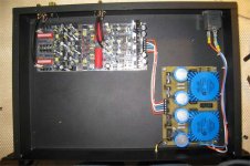
Now I understand why you have problems with grounds: that socket with filter inside is meant for SMPS. In your case capacitors between 0, ground, and phase pollute your ground by garbage.
syn08 said:
Unobtanium... No wonder that kit costs (if you include all the accesories, power supply, etc...) around $2000, and you barely made it to the case 🙂
Mine costs to build end-to-end probably $300 in parts, PCB, case, etc... I could myself use a more decent case, but finding such on this continent is more difficult than sourcing SK147/SJ72.
Now I understand why you have problems with grounds: that socket with filter inside is meant for SMPS. In your case capacitors between 0, ground, and phase pollute your ground by garbage.
Re: Re: Re: Re: S/N measurements
a) In this configuration (see the grounding schematic), I have no problems with ground. Have you bothered to read the noise results?
b) What do you think is the best option for an input filter? This is what I'm currently using:
http://ecommas.tycoelectronics.com/...6pdfEnglishENG_DS_1654001_1099_EF_0406.pdf
EF1FC model.
Wavebourn said:Now I understand why you have problems with grounds: that socket with filter inside is meant for SMPS. In your case capacitors between 0, ground, and phase pollute your ground by garbage.
a) In this configuration (see the grounding schematic), I have no problems with ground. Have you bothered to read the noise results?
b) What do you think is the best option for an input filter? This is what I'm currently using:
http://ecommas.tycoelectronics.com/...6pdfEnglishENG_DS_1654001_1099_EF_0406.pdf
EF1FC model.
syn08,
A great design like this does not need much explanation, everything is done optimally. What do you dislike about it (besides manual trimming, which is not a big deal), considering that there are extremely few alternatives around worth a mention?
syn08,Could you provide an explanation as of why is this outstanding.
A great design like this does not need much explanation, everything is done optimally. What do you dislike about it (besides manual trimming, which is not a big deal), considering that there are extremely few alternatives around worth a mention?
Re: Re: Re: Re: Re: S/N measurements
No one. Just a plain straight cheap socket.
I would recommend to connect the ground lead directly to chassis, and wind both null and phase around a donut. No caps at all, except ones that you have in parallel with rectifying diodes.
syn08 said:
b) What do you think is the best option for an input filter? This is what I'm currently using:
http://ecommas.tycoelectronics.com/...6pdfEnglishENG_DS_1654001_1099_EF_0406.pdf
EF1FC model.
No one. Just a plain straight cheap socket.
I would recommend to connect the ground lead directly to chassis, and wind both null and phase around a donut. No caps at all, except ones that you have in parallel with rectifying diodes.
Lumba Ogir said:syn08,
syn08,
A great design like this does not need much explanation, everything is done optimally. What do you dislike about it (besides manual trimming, which is not a big deal), considering that there are extremely few alternatives around worth a mention?
I have at least three alternatives that perform much better than your thing and need no manual trimming. Still pondering in chosing one, you'll find out about pretty soon.
Your answer above makes me think you have no clue how that thing is working and what is the trimming actually doing.
john curl said:Beta doesn't matter, according to Scott Wurcer. 😀
Mis-understanding again as usual. Beta linearity as it relates to transfer function is not relevant here at all. Dc offset, who cares, I don't honestly think the microamps in the cartridge matter YMMV.
Wavebourn ,
Why are you angry at RFI filters?No one. Just a plain straight cheap socket.
Why do you recommend that?I would recommend to connect the ground lead directly to chassis
Lumba Ogir said:Wavebourn ,
Why are you angry at RFI filters?
Why do you assume you read my emotions?
Why do you recommend that?
Because if phase contains some garbage in respect to null it will be divided by capacitive divider in the filter and fed on the ground. If both phase and null have common mode garbage if will be summed by that capacitors and fed to the null. This was discussed many times in other threads. Filters designed for SMPS to comply UL and similar regulations protecting mains from a garbage the gear produces don't protect the gear, especially that uses asymmetrical ins/outs.
- Status
- Not open for further replies.
- Home
- Amplifiers
- Solid State
- Addressing John Curl's concerns on low noise designs