montreal said:
Nigel,
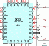
So you have 3 CXD9634Q chips labled Stream Processors where each drives 2 CXD9646Z dual power amplifier chips with 33 ohm resistors in series in each path which connects a Stream Processor chip output to a power amp chip input.
Actually I don't 'have' one, only the manual, I was replying to someone elses post. But that connection is correct.
Any chance of you posting an attachment that shows one of the three 9634 processor chips?
Yes, here it is
Attachments
Thanks Nigel for posting the diagram.
We can see that there is are four 22 ohm resistors following the 2 pairs of non-inverted and inverted outputs for the 2 channels.
That means that anyone who owns such a receiver need only attach a decoupling capacitor (say 10 microfarad) on each non-inverting output (pins 10 and 24) after the 22 ohm resistors.
Since these pins are at 2.5 volts, the polarity of the capacitor must respect this. The other side of each decoupling capacitor could lead to a RCA socket attached to the back of the case. A 100k ohm resistor could be placed between ground and the center pin of the RCA socket so that the capacitor can charge up and discharge as needed.
I can't say if there will be a DC pulse sent to the downstream equipment at turnon, but it should be easy to make sure this doesn't happen.
I guess it's time I went shopping for a Sony receiver given that Creative Labs can't seem to reveal the specs on the analog audio output of their DDTS-100 decoder.
montreal said:We can see that there is are four 22 ohm resistors following the 2 pairs of non-inverted and inverted outputs for the 2 channels.
That means that anyone who owns such a receiver need only attach a decoupling capacitor (say 10 microfarad) on each non-inverting output (pins 10 and 24) after the 22 ohm resistors.
Yes, it's simple to do - except it's COUPLING capacitors you are adding, not DECOUPLING ones. As the 22 ohms are insignificant, I originally posted the amplifier circuit, so it could be connected there - on the basis it's probably easier than a SM chip?.
Personally I would probably like to see a buffer after the capacitor, but it depends what you're feeding to?
Nigel Goodwin said:
Personally I would probably like to see a buffer after the capacitor, but it depends what you're feeding to?
I agree we probably need an opamp to follow each output.
Good luck and thanks for your postings.
Nigel Goodwin said:
Personally I would probably like to see a buffer after the capacitor, but it depends what you're feeding to?
Nigel,
It has been a few months since we let this thread go to sleep.
I have just learned that the CXD9646 is not a pure analog dual power amp chip, but a digital swtiched dual power amp which is driven by a stream processor (typically a CXD9634) which generates (an inverting and non-inverting) pulse width modulated (PWM) signals for the CXD9646.
Therefore, if my goal is to tap pin 8 on the CXD9646 to derive my PRE-OUT signal for my external power amp, then I had better recognize that the signal at pin 8 is not analog, but rather a digital signal with a variable pulse width and the pulse widths may be measured in micro-seconds.
If the two amps in the single CXD9646 package are to operate in a bridged configuration using a single polar power supply, then I imagine that for the bridge to generate the maximum possible signal (full on), then that would call for sending a 100% duty cycle pulse to one power amp and a 0% duty cycle to the other amp.
When idling, that would imply that each amp receives the same 50% duty cycle signal (with each signal in phase with the other) which would set the voltage at the each of the speaker terminals at 13.6 volts, this being half the supply voltage.
It is not clear to me how this 13.6 volts at each speaker terminal would appear on a scope. Would we see a steady DC voltage as the result of low-pass filtering or a steady stream of rapidly and constantly switching between 27 volts and zero volts (50% duty cycle)?
You're talking about 'class D', between the output of the amplifier and the speaker is a low pass filter, this removes (most!) of the high frequency switching, and leaves the audio to feed the speaker.
Nigel Goodwin said:You're talking about 'class D', between the output of the amplifier and the speaker is a low pass filter, this removes (most!) of the high frequency switching, and leaves the audio to feed the speaker.
Do you agree that the CXD9646 is a class D dual amp?
In the following link, I've learned how a pair might be bridged and filtered and the impact of any high frequency residue that remains after the low pass filter.
http://www.audioholics.com/techtips/audioprinciples/amplifiers/SwitchingAmplifierBasics2.php
However, my interest remains the creation of the PRE-OUTs and now I realize that if I build a new LC low pass filter to clean up the signal that I plan to steal from pin 8 of CXD9646, then if there is a residue that enters my external power amp, then we are talking about noise in the 350 khz. region.
I'm not sure how my external power amps will react to such noise and if I should be now looking for a Surround Sound receiver which does not use class D power amp chips.
Thanks for answering.
Thanks Nigel for your opinion.
I posted a new thread in the Class-D forum hoping that someone can advise me on how to adequately filter out the switching noise in the signal I will be trying to steal from the input of the CXD9646.
I posted a new thread in the Class-D forum hoping that someone can advise me on how to adequately filter out the switching noise in the signal I will be trying to steal from the input of the CXD9646.
montreal said:Thanks Nigel for your opinion.
I posted a new thread in the Class-D forum hoping that someone can advise me on how to adequately filter out the switching noise in the signal I will be trying to steal from the input of the CXD9646.
Assuming it's just the same signal that's coming out of the speaker outputs?, then you just need a low pass filter - but as it's at a low level you can filter it much more effectively using an opamp filter.
If you still just want DD decoding, might I suggest that you look for a used Harman Kardon AVR55. You can probably score one for $75-$130 from ebay, and it has very low noise/clean output from the pre-amp outputs. I don't know why you would want to, but it's also very easy to tap into the analog feed and bypass the amplifier modules in this product. It has easily accessible series of ribbon wires feeding the amplifier modules.
-Chris
-Chris
Nigel Goodwin said:
Assuming it's just the same signal that's coming out of the speaker outputs?, then you just need a low pass filter - but as it's at a low level you can filter it much more effectively using an opamp filter.
Yes, it would be the same signal as the final output but simply a lower voltage which could be filtered by an opamp.
I have the diagram for my Sony SACD player and the final stage is an opamp driven by a CXD9675 DAC.
The DAC sends an inverting and an non-inverting signal to each opamp, but I have no idea if this signal is a pulse width modulated type (like the signal fed to the CXD9646 chip referred to above) or a simple analog signal. If this opamp is in fact a low pass filter, then it would serve as a good model for my PRE-OUT interface.
Thanks for your suggestion.
WmAx said:If you still just want DD decoding, might I suggest that you look for a used Harman Kardon AVR55. You can probably score one for $75-$130 from ebay, and it has very low noise/clean output from the pre-amp outputs. I don't know why you would want to, but it's also very easy to tap into the analog feed and bypass the amplifier modules in this product. It has easily accessible series of ribbon wires feeding the amplifier modules.
-Chris
Thanks for your suggestion.
Just to show how hard it is for me to decide on which receiver to hot rod, a local store has a second hand Yamaha receiver with pre-outs already built into it selling for $300.
So I did some research on this model and among over 100 reviews from owners, it became clear that the power amp section was lacking (I would be bypassing that anyway), and the DSP does not always convert stereo into multi-channel surround with the best of results.
In the end, I concluded that I what I really wanted was a receiver which had the same quality and features as my Sony SACD/DVD player which has on-board DD/DTS decoding, Bass management, and a great surround sound DSP for converting stereo to 5.1.
I believe that the Sony STR-DG500 receiver has all of these advantages for $300 or less and this appears to be my best choice at the moment.
It seems that this model STR-DG500 does not have the same chips as the European receiver that we have been discussing in this thread. Most likely it has traditional analog power amps inside and I would have to take a fresh look at its schematic diagram before proceding.
One advantage with the STR-DG500 is that I might not need to build a low pass filter for each channel as would be required if the chosen receiver used the CXD9646 power amp chip.
The STRDG500/600 has discrete output transistors, with driver IC's, but according to the manual it doesn't have line level decoded outputs - but it does have multi-channel inputs for an external decoder.
Nigel Goodwin said:The STRDG500/600 has discrete output transistors, with driver IC's, but according to the manual it doesn't have line level decoded outputs - but it does have multi-channel inputs for an external decoder.
Nigel,
Thanks for your update.
My problem is I have no external decoder and because I need to decode the SPDIF output of my high definition cable box, I need to purchase a receiver which has a good quality internal Dolby decoder. Because I do not have a sub-woofer (my three 15" Tannoys generate all the Bass that I need), the receiver must also have a good DSP so I can configure my unique combination of speakers correctly. Fortunately, the STR-DG500 can do all this and more.
But I want to keep on using my external high quality power amplifiers, so I need to tap the 5.1 signals within the receiver and re-route them to the exterior.
Originally, any receiver which included your CXD9646 chip looked like a good choice for me, but now I realize that this chip only comes with more expensive receivers and transforming the PWM format signal into analog requires building a number of low pass op-amp filters.
Going with the STR-DG500 seems to be a better option for me, and from what I have learned today, the dual pre-driver ICs appear to be easy to tap into. There is also an internal buffer for the sub-woofer output which serves as a good model.
Like with any mod that creates pre-outs, I will have to make sure there is no thump in my speakers when I power up the receiver. Normally this is accomplished by adding a mechanical relay in series with the pre-out signals.
This receiver sells in Canada for $300 or less plus VAT, about twice the price of a Creative (Soundblaster) External Dolby decoder for which I have no proof of the sound quality.
Thanks for taking the time to answer.
Nigel Goodwin said:The STRDG500/600 has discrete output transistors, with driver IC's, but according to the manual it doesn't have line level decoded outputs - but it does have multi-channel inputs for an external decoder.
According to several reviews, the output power of the STR-DG700 goes down with multichannel input - as low as 5 W / channel. Sounds like either too small a transformer or heavy RL filtering before the reservoir caps.
What kind of driver IC and output transistors are used?
capslock said:
According to several reviews, the output power of the STR-DG700 goes down with multichannel input - as low as 5 W / channel. Sounds like either too small a transformer or heavy RL filtering before the reservoir caps.
What kind of driver IC and output transistors are used?
The STR-DG800 and STR-DG500 use the UPC2581 driver IC.
They both use complimentary MN2488 and MP1620 output transistors, which appear to be darlington types.
The plus/minus power supply voltage is 56V for the model 800 and 53.7V for the model 500 chassis.
The power transformer feeds directly to a dual rectifier bridge followed by a 10,000 micro cap on each pole. There does not appear to be any RL filtering.
If this receiver gets starved for power when all 5.1 channels are being driven, I would conclude that it is the power transformer that is undersized for peak demands.
I have my parts gathered for 5 pre-out buffer amps that will tap the driver ICs, but I will not start the construction until the 12 month Sony warranty is expired.
Thanks, that saves me having to buy one to find out. I would propably have to redo all output stages, so then it might be easier to stay with my Onkyo and add a variable digital delay IC.
The power reduction stated in two articles sounds too much to be attributable to filtering or an inadequate transformer. Maybe something in the circuit reacts strangely to slighlty reduced supply voltage?
Following each power stage is a DC detector circuit and an overload detector circuit. After these are mechanical relays to cut the outputs to the speaker terminals.
I can't say if the detector circuits merely switch off the relays or cause the DSP to lower the volume going to the power amplifier, or both.
It would be nice to know exactly what the laboratory testing this receiver observed when all 5.1 channels were driven.
When the volume level was raised, did the output waveform begin to clip, or did the waveform remain clean but the voltage level was automatically reduced to keep the average power to all channels from rising above a threshold?
- Home
- Source & Line
- Digital Source
- adding pre-outs to an inexpensive HT receiver.