Decrease pot's value and try again. Say, take 50K instead of 500K. Or use an audio taper pot instead of linear taper one.
I would suggest you to take direct output from the 1'st opamp (buffer) instead of from input.
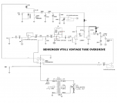
I supose that you talk about the OUTPUT of the first opamp. Just between the two 680K resistors?
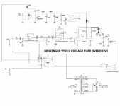
Well, I have try and try and the only way I was able to do it with a DPDT is by connecting it where the input was (See attachment No4).
There is a ground problem when the effect is off. I don't know where to connect the ground. I don't even know if this is possible.
The other option I have inspected concern the use of a 3PDT switch (See attachment No5).
Thanks for the advice about the pot. It is already a log pot in fact. I'll try a smaller value.
I supose that you talk about the OUTPUT of the first opamp. Just between the two 680K resistors?
Well, I have try and try and the only way I was able to do it with a DPDT is by connecting it where the input was (See attachment No4).
There is a ground problem when the effect is off. I don't know where to connect the ground. I don't even know if this is possible.
The other option I have inspected concern the use of a 3PDT switch (See attachment No5).
Thanks for the advice about the pot. It is already a log pot in fact. I'll try a smaller value.
Attachments

Last edited:
Ouch, I see the problem now: do you really have 100 pF cap across the pot?
Short it.
The ground should be always connected.
Short it.
The ground should be always connected.
Ok.
Could you tell me in which way is this cap affecting the behavior of the pot? It is not all clear to me.
What about the 3PDT schema?
Could you tell me in which way is this cap affecting the behavior of the pot? It is not all clear to me.
What about the 3PDT schema?
As a side comment, you don't need the capacitor in series with the transformer primary. That line already is blocked from DC.
Thanks to all of you.
I removed the LT cap and the cap connected in serie with the gain pot.
Here is the result.
So it is getting better and better but I feel a bit frustrated regarding the reasons of thoses mods (specially regarding the behavior of the 100 pF cap).
I was also wondering how this schema would work with a +12 volt instead of the actual +9V (seems to be a good way to improve the behavior of this effect)?
Attachments
Last edited:
What you have should work, except when the unit is OUT you may not have enough level from the line out, which should be more than 1/2 Volt. You are taking what I believe is an instrument pickup and trying to get line out level, not possible. You need some gain.
As for raising the voltage to 12 Volts, well I assume the 9 Volts is to get some clipping; thus you will have to go to a higher level before clipping occurs.
I am so used to trying to make amplifiers do a clean job that I find it hard to work with anyone who deliberately wants distortion. Music sounds so much better undistorted, I think.
Thanks bob for your point of vue.
I know this polemic on distortion is on the grill since decades. If you look at the recording history, lots of famous records takes there succes in the fact that the tape rec or the amplifiers creates 'natural' distortion. It was a smooth and nice disto, nothing to do with the overcompressed, overdistortioned sound that we can actually hear. Think about the old blues records from Chicago or Mississipi, the round and fat sound they produced, this is my field of inverstigation.
What you have should work, except when the unit is OUT you may not have enough level from the line out, which should be more than 1/2 Volt. You are taking what I believe is an instrument pickup and trying to get line out level, not possible. You need some gain.
Well, that's also something I am scared off. When off, the volume 'll drop down. What if I connect after the second opamp? After the 0.1 µF cap instead of between the two 680K resistors?
P.S. :I am using a electric guitar as input (single coil)
As for raising the voltage to 12 Volts, well I assume the 9 Volts is to get some clipping; thus you will have to go to a higher level before clipping occurs.
Well, this is not a bad news. This way, it 'll probably behave much more closer to want I want. I'll give it a try soon ('ll buy iron and other stuffs next week).
hacaira,
You may find you already have 12V going into the circuit, as I can't see how 9V will power the tube filaments.
How about this plan - leave the pedal as it is. Make a new box and use that NE5532 you have to build a preamp/buffer for recording. Then you can switch your pedal on or off as you please and use the pedal's volume control to match clean and "dirty" levels. The preamp/buffer circuit would only cost a few dollars in caps and resistors. You could power it with a 9V battery, or share the other supply.
Ian
For a line out, just add an opamp. You don't even need a transformer unless you have to have isolation. Figure out how much signal you have from the pickup and it will tell you the gain you need. Of course, you sacrifice the variable gain into the line out, but you could use the control on the guitar, which would affect all outputs.
I just built a guitar amplifier and now am going to add a microphone input. I am deciding whether to add an external passive mixing box, sort of a Y thing with a volume control, to take the two inputs, or add an opamp just for the microphone (I already have that inside the amplifier, currently using only two out of a quad chip).
I just built a guitar amplifier and now am going to add a microphone input. I am deciding whether to add an external passive mixing box, sort of a Y thing with a volume control, to take the two inputs, or add an opamp just for the microphone (I already have that inside the amplifier, currently using only two out of a quad chip).
Good idea. One opamp and one transformer. Or one twin-opamp: one to amplify a voltage, another to invert polarity, outputs from both to the socket, with no transformer.
For a line out, just add an opamp. You don't even need a transformer unless you have to have isolation. Figure out how much signal you have from the pickup and it will tell you the gain you need
Are you talking about adding an opamp inside the VT911 (which seems to be bad because of oscillation) or about making a separated box?
I don't like the separated box idea, I'd like to have the line out inside the box in priority (for ease of use). What about the last schema using a 3PDT, is it not good?
It may work, try it and see how it goes.I don't like the separated box idea, I'd like to have the line out inside the box in priority (for ease of use). What about the last schema using a 3PDT, is it not good?
The line out may not need to be balanced, depending on intended use.
The purpose of transformer balanced output is to avoid ground loops, even when loaded on non-balanced input.
Yes, the balanced output is a good idea. Specially with a distortion effect.
I have change the place of the effect ground connection in order to obtain more volume on the output when effect is off.
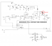
I have also found a 10pF cap on a pot situated after the cathode of the second triode (in red). Should it be removed? I still wonder what is the pruprose of theses 10 pF caps?
Regarding the difference between 9V and 12V alimentation. I see that the heaters are in serie. So they are probably using 9V instead of 12 Volt. A difference of 3,6 volt is outside acceptable range. Using 12 Volt might be another good way to upgrade this effect. I'll test soon.
I have change the place of the effect ground connection in order to obtain more volume on the output when effect is off.
I have also found a 10pF cap on a pot situated after the cathode of the second triode (in red). Should it be removed? I still wonder what is the pruprose of theses 10 pF caps?
Regarding the difference between 9V and 12V alimentation. I see that the heaters are in serie. So they are probably using 9V instead of 12 Volt. A difference of 3,6 volt is outside acceptable range. Using 12 Volt might be another good way to upgrade this effect. I'll test soon.
Attachments
Last edited:
The second cap is 10 microfarad, not picofarad. If the first one was also 10 microfarad leave it as is, it is fine. 10 picofarad would be meaningless, that's why I suggested you to short it.
The 3PDT switch will connect the line out to ground when the pedal is off, there will be no signal to record. Also you have shorted out the "gain" or "drive" pot, it will not work as drawn in the schematic.
Ian
Ian
- Status
- Not open for further replies.
- Home
- Live Sound
- Instruments and Amps
- adding line out to guitar tube preamp