Hello floks,
I have finally put my hands on the multimeter and opened the box to makes some measurements.
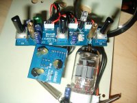
Well, as you can see on the picture, this is a tiny little piece of electronic, the kind of thing acceptable in a computer but not in a instrument effect. I really thing that it is playing a big role in the fact that it just does not sound rigth.
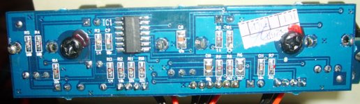
It is impossible to read the full description of the C.I. All I can see is "074".
Maybe a TL074 but it is so tiny compare to the normal one.
I don't see the reason why it is using a Quad Opamp when a double Opamp would do the job successfully? Do you have an idea on the reason of being of the two opamp marked in red? Could I bypassed them?
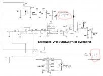
Btw, I made another correction to the map (regarding the 10 pf cap on the gain pot), it was originally a 100 pF.
And last but not least, I don't see a high voltage inductor for B+. How could it work w.o. high voltage?
Thanks.
I have finally put my hands on the multimeter and opened the box to makes some measurements.
Well, as you can see on the picture, this is a tiny little piece of electronic, the kind of thing acceptable in a computer but not in a instrument effect. I really thing that it is playing a big role in the fact that it just does not sound rigth.
It is impossible to read the full description of the C.I. All I can see is "074".
Maybe a TL074 but it is so tiny compare to the normal one.
I don't see the reason why it is using a Quad Opamp when a double Opamp would do the job successfully? Do you have an idea on the reason of being of the two opamp marked in red? Could I bypassed them?
Btw, I made another correction to the map (regarding the 10 pf cap on the gain pot), it was originally a 100 pF.
And last but not least, I don't see a high voltage inductor for B+. How could it work w.o. high voltage?
Thanks.
Attachments
Last edited:
There is nothing wrong with surface-mount circuits.Well, as you can see on the picture, this is a tiny little piece of electronic, the kind of thing acceptable in a computer but not in a instrument effect.
One provides a low impedance reference or 'virtual ground'. That is a GOOD thing.I don't see the reason why it is using a Quad Opamp when a double Opamp would do the job successfully? Do you have an idea on the reason of being of the two opamp marked in red? Could I bypassed them?
The other provides a low impedance output buffer. That is a GOOD thing. Do not bypass them.
All four opamps have a proper purpose, why would you want to bypass them??
There are no high voltages. It works from only 9V. Inductors are not necessary.And last but not least, I don't see a high voltage inductor for B+. How could it work w.o. high voltage?
Tubes can work at low voltages, but they do not usually sound very good- as you have noticed. This is a cheap product, do not expect studio quality.
Last edited:
Thanks for your answer and your enlightenments.
Do you think that I can change B+ to more or less 120 V without changing parts or does it need a complete redrawing?
I see that they are differents drawing using 65v or 120v to aliment B+, could you recommend one (I want the less noise possible and a smooth overdrive (for blues))?
Thanks
Do you think that I can change B+ to more or less 120 V without changing parts or does it need a complete redrawing?
I see that they are differents drawing using 65v or 120v to aliment B+, could you recommend one (I want the less noise possible and a smooth overdrive (for blues))?
Thanks
Hello everybody,
I have decided to completely redraw this pedal using the drawing attached.
I have tested it today but unfortunately, it does not work.
I have tested voltage on several points and it is showing 12 Volt (seems ok).
The problem could be the heaters. I have strap the pin 4 and 5 of the tube socket and placed the + from the power supply to pin 9 and the - to pin 4.
The multimeter is showing 12 Volt when testing between pin 9 and 4 (or 5) of the tube socket but the heaters does not come hot (even after 30 minutes) and it is not glowing orange.
I have tested the tube (12AX7) and it seems OK (appr. 0 Ohms between 9 and 4,5).
I cannot understand what's wrong, any idea?
Also, I am wondering why is the 18,1 W resistor used for?
Thanks
Attachments

Last edited:
about vt911 and tube replacement
Hello!
I'd like to know more about the tube you replaced and the better sounds you obtained.
Could you please specify the exact tube you've installed?
What are the main differences in the final sound?
Thanks, in advance.
Dear all,
I have a preamp tube (behringer vt911) wich (after replacement off the tube) give me full satisfaction.
Hello!
I'd like to know more about the tube you replaced and the better sounds you obtained.
Could you please specify the exact tube you've installed?
What are the main differences in the final sound?
Thanks, in advance.
- Status
- Not open for further replies.