I ordered the LM3875 premium kit from Audiosector a while ago and I just got it finished. Well its not completely finished but good enough to hook it up and see how it sounds. My first impression was that it sounded really good. The sound had really good mids and highs but the bottom end was lacking a little bit. I noticed that the power supply board doesn't use large capacitors like the one sold at Chipamp.com. Would adding larger capacitors make any difference? Is there a specific brand of capacitors I should be using? Is there any difference between using more expensive Jensen caps compared to cheaper ones?
Hi
I use LM 3886 boards that no one would admit to using here on this site - the cheap ones from China.
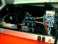
They suggest 4 x 10,000 uf caps for the power supply board but I had an opportunity to buy bigger ones - so I did - 4 x 22,000 uf.
The bridge rectifier was rated at 35 amps @ 1000 volts so - what the hell.
It's fantastic in the bass, the mid and hf.
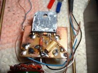
You can use whatever quality you can afford - look at the original Gaincard
picture attached to see what that means - 😉
( other one is my first effort with the bigger caps )
You'll know if it was good idea as soon as you listen to it - or not
It's a certainty that someone will explain it more scientifically and warn you
that your rectifier stage will need to cope with the extra capacitance if you go too far - I'm sure that's correct.
Regards
Andrew
Andrew
I use LM 3886 boards that no one would admit to using here on this site - the cheap ones from China.
They suggest 4 x 10,000 uf caps for the power supply board but I had an opportunity to buy bigger ones - so I did - 4 x 22,000 uf.
The bridge rectifier was rated at 35 amps @ 1000 volts so - what the hell.
It's fantastic in the bass, the mid and hf.
You can use whatever quality you can afford - look at the original Gaincard
picture attached to see what that means - 😉
( other one is my first effort with the bigger caps )
You'll know if it was good idea as soon as you listen to it - or not
It's a certainty that someone will explain it more scientifically and warn you
that your rectifier stage will need to cope with the extra capacitance if you go too far - I'm sure that's correct.
Regards
Andrew
Andrew
Attachments
I beefed up the caps in the power supply of a chipamp I built from salvage- I ripped the whole power amp board out of a fubared unit and grafted it into an integrated amp. Doubling the capaticance (to merely 10,000 uF per rail ) made a very significant difference in the bass "punch" delivered by the amp- it made the difference. This was with the original large but inefficient and hot running transformer, and the original rectifiers.
It is a concern that bigger caps can destroy or shorten the service life of the rectifiers, but that is easily rectified too (pun intended😛). If you look at the data sheet on a typical rectifier, you will see that the peak instantaneous current is at least a magnitude of 10 greater than the service rating. You must take into consideration the transformer used too; if it's a wimpy, old technology transformer, your rectifiers will probably be safe. If it's a really beefy unit, it's a good idea to upgrade the rectifiers anyway.
It is a concern that bigger caps can destroy or shorten the service life of the rectifiers, but that is easily rectified too (pun intended😛). If you look at the data sheet on a typical rectifier, you will see that the peak instantaneous current is at least a magnitude of 10 greater than the service rating. You must take into consideration the transformer used too; if it's a wimpy, old technology transformer, your rectifiers will probably be safe. If it's a really beefy unit, it's a good idea to upgrade the rectifiers anyway.
If I'm going to add some 10,000 uF capacitors to my power supply board I think I'm going to also snubberize it at the same time. I'm just not sure which value resistor and capacitors I should be using. The snubbered power supply from the Chipamp website uses different values than the ones shown in the schematic for the power supply from Audiosector. It says I should be using a 0.1 ohm resistor and a 3300 pF capacitor but the chipamp power supply has a 1 ohm resistor and 0.1 uF capacitor. Does it matter which ones I use?
I think that if you read Audiosector you will find that everything has been tailored to give maximum sound quality in the Mid and Treble ranges when driving high efficiency speakers.
Peter Daniel has omitted the smoothing capacitor stage completely from his implementation. Here he uses the local decoupling caps as the sole transient current supply. I think this seriously compromises the bass performance of the Power Amplifier.
You buy and listen to what you like. Peter's implementation may suit many, but it cannot suit every listener.
My philosophy is quite different and it too cannot suit everyone.
AndrewT
More details please !😕
My philosophy is quite different and it too cannot suit everyone.
More details please !😕
if you are prepared to research the chipamp topic, you will find I have many opinions that are not considered universal.
eg.
Chipamps don't suit 4ohms speakers.
Chipamps can't perform well if running hot.
Chipamps can produce bass if the PSU is designed to deliver current.
Chipamps don't like low efficiency speakers.
Power Amps in general need to be bandwidth limited at the input.
The NFB and Smoothing and other caps in the amplifier all interact with each other and when chosen badly and/or randomly will interfere with the performance of the amplifier.
A full range amplifier needs a far wider bandwidth than what we are capable of hearing to sound right.
Last edited:
if you are prepared to research the chipamp topic, you will find I have many opinions that are not considered universal.
eg.
Chipamps don't suit 4ohms speakers.
The unit I ripped the power amp unit out of had 6 ohm speakers. It is now driving 6 ohm speakers. I have a pirated chipamp circuit board (don't know how good it could sound, it's sitting in a box) that drove 3 ohm speakers. Both of these amps have "no name" chips with no markings on them.
I have looked at a lot of your posts, Andrew, and I appreciate your perspective. Do you say this because 4 ohm speakers seriously reduce loop gain? Because a 4 ohm load will trigger the overload circuits and not allow full voltage swing into the load? Heat? Inquiring minds want to know.🙂
And I do realise that paralleling them will get around all that. My buddy was bragging about his custom built amp, 100 watts into 8 ohms, and it will deliver full current and full voltage swing into 1 ohm. In fact he has it running an array of speakers in a configuration that provides a load of 1.5 ohms "nominal." Anyway, I went over there and he opened it up, and it is a bridged/ paralleled chipamp, 10 chipamps per amplifier and beefy dual power supplies. It sounds damn clean too. Very clever and has me wanting to make a "little brother" clone of it.
Chipamps can't perform well if running hot.
I can see this. Do the parameters really shift that much with heat? Crossover distortion increase?
Chipamps can produce bass if the PSU is designed to deliver current.
I figured that out when I built my salvage part chip amp. I do have experience designing and building solid state, op amp based, and tube power amps, though. Do you think chipamps are more susceptible to this phenomenon than other amps? Why?
Chipamps don't like low efficiency speakers.
Headroom and nasty clipping?
The NFB and Smoothing and other caps in the amplifier all interact with each other and when chosen badly and/or randomly will interfere with the performance of the amplifier.
More so than other amps?
Did you read my little talk about choosing poles for the RC circuits when designing an amplifier? It's the same concept, isn't it? Because haphazard choice of capacitor values will have the same effect on a solid state amplifier too, and the more poles the amplifier contains, the worse it will be.
A full range amplifier needs a far wider bandwidth than what we are capable of hearing to sound right
No questions about this.🙂
Thanks for considering my questions, Andrew. I understand electronics pretty well, but chipamps are new to me. Evidently they're deceptively simple. Is it because it's so easy to nudge them into instability? Wouldn't conventional "common sense" design avoid this pitfall?
My first chipamp worked real good.🙂 Nothing fancy, 100% salvage parts.
I'll come back on just one point you picked up, current limiting.
Take the 3886 as an example.
The maximum output current of this chipamp is specified @ Tj=25degC and can vary from a low of 7Apk to a typical 11.5Apk.
Heat up the chipamp and this maximum current will drop.
Heat it a lot and it will drop drastically. I'll guess and suggest that at Tj~90degC, Tc~70degC, Ts~50degC the maximum current could be limited to less than 50% of the cold specification.
Now look at an 8r0 load on a chipamp and let's see if we can predict the currents that will be demanded.
68W into 8r0 is equivalent to 23.3Vac and 2.92Aac to the load.
This is 33Vpk and 4.1Apk.
Now consider a reactive 8ohm speaker load. The maximum current easily reaches double the value expected into a resistive load and in extreme (rare) cases triple and more, than what the resistive load demands.
Our 68W amp will regularly exceed 8Apk into an 8ohm speaker when played loud and occasionally exceed 12Apk. How can a warm or hot chipamp meet these demands when Spike and the other protections are overseeing the health of the Chipamp?
Change the speaker load to 6ohms and the worst case transient currents become >14Apk. The demand for current becomes greater the lower the speaker load impedance. Warm chipamps just cannot meet that transient demand. But we can help them perform. To reduce the current demand use speakers that are higher impedance, use speakers that are less reactive, use speakers that are efficient, use speakers that have a very simple crossover. this is pointing to using a full range 8ohm driver with sensitivity >93dB/W @ 1m.
Finally, of the National Series of Chipamps, the 3886 has the highest output current capability relative to it's heatsink interface thermal resistance. All others are less capable of meeting these transient current demands.
Last edited:
I just wanted to give an update because I just added some 10,000 uF capacitors to the power supply board and added the snubber components. I sat down and listened to some cd's and I honestly can't tell the difference or if it made any improvement at all. I thought a snubberized power supply with larger caps was supposed to give better bass and a more dynamic sound but it still sounds the same as before I think. Its hard to say since I couldn't do a direct comparison before and after the changes. I think there's a a bit more bass but maybe I'm just hearing things because I was expecting an improvement. Oh well it didn't cost too much for the parts so I guess it was worth trying it to see if it made any difference.
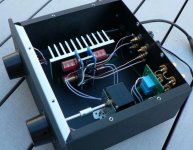
I've built a few of Peter's LM3875 kits and found I preferred it with the 1500uF caps on the power supply PCB (replaces the 10uF) and installed 100uF Elna Cerafines on the amp PCB near the chip. If you look at Peter's commercial amps, it uses this arrangement. See the pic for the caps on the amp PCB that were changed.
I did try a snubbered power supply but seemed to lose some character in the mids and as well as had an odd tonal balance..... over blown maybe.
For lower impedance speakers I found lower voltage power supplies using a 18VAC-0-18VAC transformer works well but you do lose power (but gain current).
I did try a snubbered power supply but seemed to lose some character in the mids and as well as had an odd tonal balance..... over blown maybe.
For lower impedance speakers I found lower voltage power supplies using a 18VAC-0-18VAC transformer works well but you do lose power (but gain current).
Attachments
I might try changing out the capacitors on the amp board with some of those Elna Cerafine capacitors. I think I'm going to experiment a bit with leaving the snubbers in but using 1000uf caps on the amp board instead. Or removing the snubbers and using 1500uf caps on the power supply and 100uf on the amp. My question is what voltage rating for the caps do I need for the amp board? Is 35v ok? The reason I'm asking is because 35v is the highest I can get for some of the capacitors.
Last edited:
I don't go below 50V caps on these amps.
If your rails are above 30V I'd hesitate using 35V caps.
If your rails are above 30V I'd hesitate using 35V caps.
Would adding larger capacitors make any difference?
In the Patek he was using BG N 100/50 (CAP-9360) near the amp and BG STD 1000/50 (CAP-9120) near the rectifiers. That's what I am using.
rabbitz:
Did you move the original 1500uF 50v Panasonic FC Capacitors from the amp to the power supply and then buy the Elna 100uf's to replace those?
How does it sound differently with that arrangement SimonKit and rabbitz?
Did you move the original 1500uF 50v Panasonic FC Capacitors from the amp to the power supply and then buy the Elna 100uf's to replace those?
How does it sound differently with that arrangement SimonKit and rabbitz?
Last edited:
On my later builds I used the 1500uF on the power supply and 100uF Elna on amp.
With this arrangement I found the sound to have better bass control, better focus and more body to the sound but others prefer it the other way. I could never understand the use of the 1500uF cap on the amp where on all my other SS amps, the power supply has the larger caps and the amp the smaller caps. I don't remember the history of why the amp had the 1500uF caps but suspect was due to the original GainCard.
With this arrangement I found the sound to have better bass control, better focus and more body to the sound but others prefer it the other way. I could never understand the use of the 1500uF cap on the amp where on all my other SS amps, the power supply has the larger caps and the amp the smaller caps. I don't remember the history of why the amp had the 1500uF caps but suspect was due to the original GainCard.
if you are prepared to research the chipamp topic, you will find I have many opinions that are not considered universal.
eg.
Chipamps don't suit 4ohms speakers.
Chipamps can't perform well if running hot.
Chipamps can produce bass if the PSU is designed to deliver current.
Chipamps don't like low efficiency speakers.
Power Amps in general need to be bandwidth limited at the input.
The NFB and Smoothing and other caps in the amplifier all interact with each other and when chosen badly and/or randomly will interfere with the performance of the amplifier.
A full range amplifier needs a far wider bandwidth than what we are capable of hearing to sound right.
Well, I just love this post!
I would agree with all of that except that I would like to add a couple of exceptions to the 4 ohm statement:
1). Paralleled chip amps
2). Inverted LM3886 (decibel dungeon examples make excellent woofer amps) or non-inverted TDA7294 (definitely not the awful datasheet design), when the power supply and amplifier design is specifically accommodating to handle the 4 ohm speakers.
Certainly the common kits don't support 4 ohm speakers, but there's a lot that the kits don't do because most kits are parts, as in not ready to run like a complete amplifier.
Bass with the common chip amp kits:
The slight actuance instability used in the 47 labs and LM3875 kits working like a photoshop sharpening filter to artificially increase the clarity of the midrange at the expense of some heat and disproportionately louder midrange, in addition to the LM3875 kit's missing input circuit that's not at line level until you force it as well as the two bass blockers inbuilt to the LM3886 kits which also don't come with a sensible input circuit. . . are all "cart before horse" examples of when you need to patch the amplifier design before considering adding additional capacitance to the power supply board.
As for speaker efficiency, the 2-way speaker's efficiency becomes a moot point as soon as woofer excursions have shaken and distorted the voice band. It is unnecessary to increase the efficiency of a distortion.
Now, don't curse me on that one before you go and ask a professional singer about the issue. Be prepared for a surprisingly sudden rant!
Because of that real-life data, I have to claim that LM1875 has more than enough power for an 8 ohm 84db 2-way speaker.
For speaker efficiency, let's consider 3-way speakers, and yes, a highly efficient 3-way speaker makes up for the typical lackluster dynamics of the common chip amplifier implementations.
Its not exactly necessary to design a chip amplifier that needs efficient speakers for lifelike music, because its certainly possible to design the amplifier otherwise, with one big caveat. . .
The poor dynamics chip amplifier results from the datasheet designs whereby the amplifier is made to operate directly at line level without a buffer or preamplifier.
-compare to-
The high dynamics chip amplifier will have an input load of 100k, a feedback resistor at or beyond 100k, it will always have an NFB cap like a traditional amplifier, it will have a full scale power supply with PI filter, and it will have the traditional full implementation of an output filter. And, unfortunately, it will require a buffer, a preamplifier or a matching transformer at its input. The big caveat is that a source designed for 10k line level outputs 10 times less current to an amplifier with 100k input load. Not all sources are incompatible with 100k loads; however, a good amplifier would be matched to 10k line level spec. With many sources, you'd need some way to make up for this factor of 10 less current or else your bass is gone. This problem brings back the old topic of impedance matching, but it also brings back your dynamics.
Therefore not all chip amplifiers need efficient speakers, not all are allergic to 4 ohm speakers, and not all run hot.
In fact, the temperature may be the most important aspect. The hot running chip amplifier is hot because its making distortion rather than amplifying only audio.
So, I would agree with everything that AndrewT said except for the 4 ohm speakers. However, all of the amplifier caveats, especially temperature (stability and noise), need to be overcome prior to connecting the 4 ohm speakers.
For example:
The paralleled chip amplifier with 4 ohm speakers is the "easy way out" for forcing real dynamics out of the common amplifier datasheet designs that can operate at line level without a preamp. This amplifier has the highest current on both input and output; and current makes dynamic bass.
Caveat: If the amplifier wasn't designed to handle the current then the 4 ohm speaker will force it much like using a plunger on a dodgy commode with a too small port. Results can vary.
I understand why "Chipamps don't suit 4ohms speakers" was on AndrewT's list. Supporting more difficult speakers requires extra attention to detail--which is very much uncommon in chip amplifiers.
Lets just say that I mostly agree with him, and this much:
If he made a chip amplifier kit, I'd be first on the waiting list to buy it.
Power noise--fixing the actual problem:
Recently I helped a guy with this problem.
Caveat with MUR860's is noise because they're not for use in linear power supplies; however, they are excellent for marketing purposes.
(8) Using 8 with a dual secondaries transformer is what the kits specify, and if you're lucky, this equal and opposite will cancel some noise.
(4) Using 4 with a center tap transformer makes increased voltage spikes whereby the rectifier seems to be remarkably more efficient at making extra voltage but this is actually just extra noise and will get the chip-amp extra hot.
(2) Using 2 with a center tap transformer (see the wikipedia example) is what the 47 labs amplifier specifies for a simulated tube rectifier, but this also seems to run hot.
Problems:
The heat is problematic for the Spike system which makes a clipping noise upon the midrange audio output, and the noise of the power circuit also makes extraneous and louder distortion on the midrange audio output. This MUR860 component's high noise output is causing the amplifier to have unlevel frequency response with an insufficient proportion of bass. However, the effect of this also makes the amplifier more dynamic--that's useless if you don't want to hear it screeching though.
So, yes, adding the 10,000uF or more extra capacitance might quash that rectifier noise but a Pi filter is more specific to getting rid of that particular problem (so use the resistors in addition to the big caps).
Or the easy way might just be to get rid of the noisy rectifier.
For a more seemly alternative rectifier and 4% less distortion, see the Mark Houston Synergy Gainclone project. That cute little plastic square with its inexpensive little polyester dip caps might not be marketable to the highbrow people, but it sure will make for cleaner power, a cooler amplifier and a more level frequency response. 🙂 Yes you can use one for a center tap transformer or two for a dual secondaries transformer.
The LM3875 and LM3886 are capable of fighting off the noise from the inbuilt Spike circuit if the chips are used in parallel mode (turns noise into heat) because the inbuilt noisemaker doesn't sound off at exactly the same time on both chips. Harnessed in tandem like that, they're almost noise free, and they also produce sufficient current. Due to the added heat, I'm sure you'd want to provide it with clean power.
The topic seems to be every way under the sun to stop power noise. Well, fixing that directly just might make for quicker results.
Last edited:
I just wanted to give an update because I just added some 10,000 uF capacitors to the power supply board and added the snubber components. I sat down and listened to some cd's and I honestly can't tell the difference or if it made any improvement at all. I thought a snubberized power supply with larger caps was supposed to give better bass and a more dynamic sound but it still sounds the same as before I think. Its hard to say since I couldn't do a direct comparison before and after the changes. I think there's a a bit more bass but maybe I'm just hearing things because I was expecting an improvement. Oh well it didn't cost too much for the parts so I guess it was worth trying it to see if it made any difference.
The Pi filter component is missing.
It kind of goes like this:
transformer
rectifier
smoothing caps
pi filter (a simple series resistor)
big tank caps
interconnect cable
amplifier board
local smoothing caps
You can optionally knock some power noise out by using 2uF to 4.7uF capacitors with at least 100v tolerance directly from V+ to V- at the amplifier boards and this will decrease some midrange noise; however, the amplifier is already making the maximum amount of bass, so if you want to hear more bass, it will be because of decreasing the midrange proportion.
If two similar linear amplifiers are presented with the same load, the one that runs cooler at the heatsink is probably more stable and with less distortion than the other. Specifically, the LM3875 is usually exploited via a very slight instability as an actuance device to increase the perceived clarity of the midrange. Consider what happens if you repair that. It will run cooler, with a more level frequency response, but it will be ordinary.
Danielwritesbac - I'm sorry but I just can't make any sense of what you're saying. It just seems to be a series of random thoughts written down with no connection between them.
Is it just me or does anyone else have this problem with Daniel's contributions?
Is it just me or does anyone else have this problem with Daniel's contributions?
- Status
- Not open for further replies.
- Home
- Amplifiers
- Chip Amps
- Adding larger capacitors to Audiosector LM3875 kit