adding Digital audio transmitter to B&O CD50
Hi
I want to build and external DAC for my old CD50, but this old player havent got a digital output. Chipset is YM3511,YM2201,PCM53JP. I have the schematics and a picture block diagram of the ym2201 and it looks like there are three unconnected pins for it.... on the board is an unmounted connector with SDSY,SDO,CLK2 and de-emph. The data streams look like this (looks od in forum copy text to notepad ).
1 2 3 4 5 6 7 8 9 0 1 2 3 4 5 6 7 8 9 0 1 2 3 4 5 6 7 8 9 0 1 2 3 4 5 6 7 8 9 0 1 2 3 4 5 6 7 8 9_
SDSY (sYNC LEFT/RIGHT)
HHHHHHHHHHHHHHHHHHHHHHHHHHHHHHHHHHHHHHHHHHHHHHHHLLLLLLLLLLLLLLLLLLLLLLLLLLLLLLLLLLLLLLLLLLLLLLLLLL
SDO (DATA)
HHHHHHHHLLLLHHLLLLHHHHLLLLLLLLLLLLLLLLLLLLLLLLLLHHLLLLLLLLHHHHHHLLLLHHLLLLLLLLLLLLLLLLLLLLLLLLLLLL
O2 (CLK)
HLHLHLHLHLHLHLHLHLHLHLHLHLHLHLHLHLHLHLHLHLHLHLHLHLHLHLHLHLHLHLHLHLHLHLHLHLHLHLHLHLHLHLHLHLHLHLHLHL
Is this left justified datastream ? when SDSY is high the CLK shifts 24 times and when SDSY is low it shifts 25 times, is this normal ?
Best regards Kim Olesen
www.micro-io.dk
calculating...
(24+25)*44100*4 = 8643600, this is the YM2201 crystals speed to.
Will this output be accepted be a DIT4096 or CS8406 ?
Best regards Kim Olesen
www.micro-io.dk
(24+25)*44100*4 = 8643600, this is the YM2201 crystals speed to.
Will this output be accepted be a DIT4096 or CS8406 ?
Best regards Kim Olesen
www.micro-io.dk
You won't be able to feed that into a DIT4xxx or CS8406 directly.
You'll need a PLL to convert 8643600 to 44.1*256 to create a clock for the transmitter, and and a bit of logic to convert that bitstream into RJ, LJ or some other format which a DIT can understand.
I don't know anything about the format, so it's hard to say what logic is needed. You might be able to do it with a bunch of 74xx, a CPLD, a FPGA, maybe even a cheap DSP chip.
Hi
Thanx for !
I have looked through some yamaha datasheets today, and i your right..
Would it not be better to make a low jitter clock at 44.1khz*256 and a PLL to replace the 8.6436Mhz crystal and then convert the 24+25bit of into 32bit+32bit carrying the two 16bit for L/R only, with some logic or a microprocessor running at the 11.2896Mhz clock?
Best regards Kim Olesen
www.micro-io.dk
Hi
CS8406 and a 11.2896Mhz oscillator might be it! CS8406 datasheet page 14
"In slave mode, the left/right clock and the serial bit clock are inputs. The left/right clock must be
synchronous to the OMCK master clock, but the serial bit clock can be asynchronous and discontinuous
if required. The left/right clock should be continuous, but the duty cycle can be less
than the specified typical value of 50% if enough serial clocks are present in each phase to clock
all the data bits."
I have 16bit data left adjusted and a left/right clock with 48.97% duty cycle... and enough serial clock cycles!
Best regards Kim Olesen
www.micro-io.dk (SE tube amplifier with multiple primary windings )
Hi
At last i got time to try this out. have built a 11.2896Mhz VCO, a PLL and a low jitter 8.6436Mhz clock for the player. I have connected a CS8406 to YM2201, but the only sound i get i a loud "hiss" noise. The CS8406 is running in hardware mode and it triggers at rising clock edge and it looks like my clock is inverted. I tryed an inverter first, the same output but when hooking up a scope to the clock input i can hear some music burried in noise. tried two inverters after each other to see if the propagation delay would help. Now it plays some music burried in noise.
Ok the PLL is not in lock yet, as the original 8.6436Mhz xtal was running 2khz higher, but the Cs8406 should repeat lost frames.
any ideas on what could be the problem ?
Best regards
Kim Olesen
Hi
No datasheet, only a block diagram, and ofcourse the cd50 service manual. The player's pcb has a lot of missing components and the 4 signals (data,clock,LRclock,deemp) ends in a 4way header so it might have been prepared for digital out. The drive is from Aiwa and the electronis is from japan, and modifyed with a b&o cpu board and some other things. I have tried to find a yamaha digital audio transmitters from 1983-85, but no luck (the player is that old ) , as these could help finding some description of he protocol.
I can take a few pictures of the data (from logicdartprobe screen) if this can help to find the right protocol.. data seems to be 16bit left adjusted.
best regards
Kim Olesen
www.micro-io.dk
No datasheet, only a block diagram, and ofcourse the cd50 service manual. The player's pcb has a lot of missing components and the 4 signals (data,clock,LRclock,deemp) ends in a 4way header so it might have been prepared for digital out. The drive is from Aiwa and the electronis is from japan, and modifyed with a b&o cpu board and some other things. I have tried to find a yamaha digital audio transmitters from 1983-85, but no luck (the player is that old
) , as these could help finding some description of he protocol.I can take a few pictures of the data (from logicdartprobe screen) if this can help to find the right protocol.. data seems to be 16bit left adjusted.
best regards
Kim Olesen
www.micro-io.dk
They don't ! the serial signal continues inside the chip to a digital filter/oversampling and from there to paralel output.. included a picture of the 2 chips used and a YM3015 serial DAC
is there other codes than 2' complement there have been used for cd ?
Maybe it is possible to burn a cd with sinus or square signal so that i have a repeated signal to measure at.
best regards
Kim Olesen
is there other codes than 2' complement there have been used for cd ?
Maybe it is possible to burn a cd with sinus or square signal so that i have a repeated signal to measure at.
best regards
Kim Olesen
Attachments
Hrmmm yes why..... Just beside the YM2201 chip there is placed a 4 way header with CLOCK/DATA/LRclock/De-emp... Ofcourse i could be wrong but it look like it is the 4 signals needed to send serial data, and ofcourse the data could be some crap.
hooking up a logic analyser to the pins show data in the first 16 clock cycles of each LR frame, sometimes a databit in the last position of the frame.
Best regards
Kim Olesen
hooking up a logic analyser to the pins show data in the first 16 clock cycles of each LR frame, sometimes a databit in the last position of the frame.
Best regards
Kim Olesen
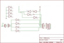
okay i have done some research on the cd50 board.. there is two missing chips and some headers and the analog phono output (rewired to DINconnector) and another connector is missing. Included a schematic of what i guess is missing, take a look.... ic pin numbers fit a 74**04 .
The player is old, i remember that when it came on the marked other companys had just begun with digital out. So it might be some jurassic data output.
best regards
Kim Olesen
The player is old, i remember that when it came on the marked other companys had just begun with digital out. So it might be some jurassic data output.
best regards
Kim Olesen
Attachments
LR clock is 44.1Khz. Clock is (44100*(24+25)) = 2.1609Mhz. there is 24bit when LR is high and 24bit when LR is low.
Best regards
Kim Olesen
Best regards
Kim Olesen
KimBOlesen said:LR clock is 44.1Khz. Clock is (44100*(24+25)) = 2.1609Mhz. there is 24bit when LR is high and 24bit when LR is low.
Best regards
Kim Olesen
A curious figure, how did you arrive at it ? Are you sure clock is not 48Fs (2.116800MHz)?
Nope...
Logicanalyser and a scope shows the trace in answer#1. Xtal is 8.6436Mhz, divide this by 4, and then divide by 49 you get 44100hz.
Best regards
Kim Olesen
Logicanalyser and a scope shows the trace in answer#1. Xtal is 8.6436Mhz, divide this by 4, and then divide by 49 you get 44100hz.
Best regards
Kim Olesen
KimBOlesen said:Nope...
Logicanalyser and a scope shows the trace in answer#1. Xtal is 8.6436Mhz, divide this by 4, and then divide by 49 you get 44100hz.
Best regards
Kim Olesen
I think you have the cart before the horse. It is far more likely that FS is not exactly 44100 than serial clock is 49Fs. What does it say on the xtal?
KimBOlesen said:Nope...
Logicanalyser and a scope
Best regards
Kim Olesen
What are you triggering the scope with?
- Status
- Not open for further replies.
- Home
- Source & Line
- Digital Source
- adding Digital audio transmitter to B&O CD50