Hi Folks.
A friend asked me to add a volume pot to an amp his father built many years ago. I don't have a schematic for it, but basically it is a single ended stereo amp with a 6SL7 as the driver and 2X 6L6 as the power tubes, one per channel. He wants to be able to use it with a CD player that does not have a variable out. I have a 100K Alps pot I would like to use, and a 50K and a 250K in pots of lesser quality. My main concern is what to do with the resistor that goes from the input to ground. It has a value of 220K. Do I leave this resistor, and put the pot after it and then put the output of the pot to the grid of the driver tube? Do I attach the pot to the input and then put the 220K resistor from the output of the pot to ground and then hook up to the grid? Do I remove the 220K resistor to ground and replace it with the pot? What is the purpose of this resistor? I have built amps with resistors in series between input and grid, and with the normal volume pot set up, but this is new to me. Any advice would be appreciated.
A friend asked me to add a volume pot to an amp his father built many years ago. I don't have a schematic for it, but basically it is a single ended stereo amp with a 6SL7 as the driver and 2X 6L6 as the power tubes, one per channel. He wants to be able to use it with a CD player that does not have a variable out. I have a 100K Alps pot I would like to use, and a 50K and a 250K in pots of lesser quality. My main concern is what to do with the resistor that goes from the input to ground. It has a value of 220K. Do I leave this resistor, and put the pot after it and then put the output of the pot to the grid of the driver tube? Do I attach the pot to the input and then put the 220K resistor from the output of the pot to ground and then hook up to the grid? Do I remove the 220K resistor to ground and replace it with the pot? What is the purpose of this resistor? I have built amps with resistors in series between input and grid, and with the normal volume pot set up, but this is new to me. Any advice would be appreciated.
I would leave the grid leak resistor where it is and connect the wiper of the pot, through a 100nF cap to the grid, cold side of the pot to the ground, on the 220k resistor and your signal to the hot side.
Yes. Leave the existing 220k grid leak resistor in place. Put the volume pot before it and add a coupling capacitor from pot wiper to first grid. You will see many circuits which omit the cap and the 220k, but these can eventually lead to excess noise due to grid current affecting the pot.
Thanks. I will do as you recommend.. There is no cap there currently. I suppose that it would have to be a high quality one as it would be directly in the signal path. it strictly necessary to add one?
Almost everything in a valve amp is 'in the signal path' so 'in the signal path' is not a useful concept unless used very carefully.
The cap is a coupling cap, with low signal voltage and almost no DC voltage, so any decent film cap will do. It is necessary if you want the volume pot to have a long and happy life.
The cap is a coupling cap, with low signal voltage and almost no DC voltage, so any decent film cap will do. It is necessary if you want the volume pot to have a long and happy life.
The signal cap. to be added will probably not be exposed to DC. "Run in" might be problematic. With that info. in mind, I suggest you use a polystyrene film part. The amp's I/P resistor is 220 Kohms and a 0.15 μF. part will avoid phase shifts inside the audio band.
Full compliance with the 1:10 rule requires the resistance of the pot. to be <= 22 Kohms. A commercial CDP will drive the IHF "standard" of 10 Kohms. So, I suggest your friend acquire a 10 Kohm PEC of Canada hot molded carbon control.
Full compliance with the 1:10 rule requires the resistance of the pot. to be <= 22 Kohms. A commercial CDP will drive the IHF "standard" of 10 Kohms. So, I suggest your friend acquire a 10 Kohm PEC of Canada hot molded carbon control.
"Run in"? This is a coupling cap, not a 1960s petrol engine.
The 1:10 rule is guidance, not a law of physics. The 220k could always be increased to 470k.
The 1:10 rule is guidance, not a law of physics. The 220k could always be increased to 470k.
So, use the 100K pot with a 470K resistor? Or should I use the 100K pot with a 1 meg resistor? I don't understand the function of the resistor. I have built amps that have a 100K pot and a 1K resistor in series (a Decware SE84CS clone), just the 100K pot by itself (Alex Gendrano KT88), and one where I added a 100K pot to an existing 1meg to ground at the input (RH84 Rev2). None that I've built had a capacitor before the grid of the driver tube. A brief explanation would be greatly appreciated.
Leave the 220k in there and fit your pot with a series capacitor of 100n. Almost anything capacitor wise will be fine. I would use MKT1813-410-405 | Vishay 100nF Polyester Capacitor PET 200 V ac, 400 V dc 10% MKT 1813, MKT1813 Series Through Hole | Vishay
Can't go wrong with it.
Can't go wrong with it.
The capacitor prevents grid current from travelling across the wiper-track interface. Any DC current here can lead to noise developing eventually. Omit the cap and the thing will work fine for a few years, so most circuits omit it.

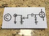
Neither. It should be like B, except that the grid resistor goes from the grid to ground rather than pot wiper to ground.
Also, if I wanted to use the 100K pot, should I increase the grid resistor value to something closer to 1 meg?
Your drawing is perfect. Leave the grid leak resistor as it is at 220k and that is ideal for any pot.
The capacitor prevents grid current from travelling across the wiper-track interface. Any DC current here can lead to noise developing eventually. Omit the cap and the thing will work fine for a few years, so most circuits omit it.
Am I right to assume this has a lot to do with "static-y" noise on old pots in cheap radios? I haven't seen many coupling caps in the input from pot to grid.
I built mine without it. 300 ohm grid stopper right into the 100k pot. If I understand properly this will lead to an early pot failure?
Thanks.
Lots of circuits omit the capacitor. Lots of circuits end up with noisy pots. All pots go noisy eventually, but pots with DC across the wiper-track interface tend to go noisy earlier. By 'earlier' I mean years rather than decades; if you frequently change your gear then this would not be a problem, but I am of the generation which expects things to last.
- Status
- Not open for further replies.
- Home
- Amplifiers
- Tubes / Valves
- Adding a volume pot to tube power amp