Hi All
Hope some of you wouldn't mind just giving me any ideas of how to go about this. I have looked through other threads and asked questions on here in them but Im not getting much joy.
I bought this little cheap tube pre amp / so called buffer and Im just having fun with it and enjoying music through it. Its basically the same board as the image links below its just mine came in a case with a power supply ready to go.
The issue I have is it boosts the signal through it a bit too much and I'd just want to attenuate it if I can. I'm not as clever as you guys on here when it comes to electronics but I can manage most tasks and soldering if I'm told what to get and do.
What I really want to know is can anyone just by looking at the board below know where would be the best place to put in a volume control in this circuit please? Or even something that just allows it to match the level of the signal going in to it, or without a volume pot even and whilst changing its sound as little as possible
It does sound fine but it is just amplifying things a bit too much. Depending on the material it can sometimes push it to being too loud and clipping, all I want to do is stop it doing that, and level matching the input would the ideal thing.
Any input will be greatly appreciated.
https://i.ebayimg.com/images/g/hxMAAOSwLsBZQNZJ/s-l1600.jpg
https://i.ebayimg.com/images/g/p1oAAOSw-29ZQNZK/s-l1600.jpg
https://i.ebayimg.com/images/g/xHkAAOSwXXxZQNZK/s-l1600.jpg
https://i.ebayimg.com/images/g/Z58AAOSwgv5ZQNZK/s-l1600.jpg
https://i.ebayimg.com/images/g/PVkAAOSwbtVZQNZK/s-l1600.jpg
A schematic is a must in order to make a rational recommendation.
Assuming a "standard" CDP is the signal source, we know a 10 Kohm volume control will be OK. Commercial CDPs must be capable of driving the IHF "standard" 10 Kohm load. What we don't know is the I/P impedance of that "buffer" unit. Long established practice requires the I/P impedance of an entity being driven to be at least 10X the O/P impedance of the driving entity. You need at least a 100 Kohm I/P impedance to be present in the "buffer".
If push comes to shove, you will have to trace the schematic out for yourself.
BTW, does the possibility of a DC offset being present in the signal source exist? If such an offset exists, a blocking cap. will be needed. A high quality/low WVDC 1 μF. film part will be needed. Soviet surplus polystyrene, if you can source it, would be excellent.
I don't have answers to all your questions as it will need some digging around for info.
But I'll bet the board you have there is the same as this one on ebay, albeit with valves mounted horizontally.

It is listed as: "Stereo Tube Preamplifier" and "This board comes with a boost" so amplifies the signal which would account for the distortion you are experiencing depending on where you have placed it in the audio path.
Having a potentiometer or 2 resistor divider network at the input would solve the distortion but it is better to reduce the gain of the circuit as the valves would be adding noise.
But I'll bet the board you have there is the same as this one on ebay, albeit with valves mounted horizontally.
It is listed as: "Stereo Tube Preamplifier" and "This board comes with a boost" so amplifies the signal which would account for the distortion you are experiencing depending on where you have placed it in the audio path.
Having a potentiometer or 2 resistor divider network at the input would solve the distortion but it is better to reduce the gain of the circuit as the valves would be adding noise.
A schematic is a must in order to make a rational recommendation.
Assuming a "standard" CDP is the signal source, we know a 10 Kohm volume control will be OK. Commercial CDPs must be capable of driving the IHF "standard" 10 Kohm load. What we don't know is the I/P impedance of that "buffer" unit. Long established practice requires the I/P impedance of an entity being driven to be at least 10X the O/P impedance of the driving entity. You need at least a 100 Kohm I/P impedance to be present in the "buffer".
If push comes to shove, you will have to trace the schematic out for yourself.
BTW, does the possibility of a DC offset being present in the signal source exist? If such an offset exists, a blocking cap. will be needed. A high quality/low WVDC 1 μF. film part will be needed. Soviet surplus polystyrene, if you can source it, would be excellent.
Thanks Eli, you make that sound like an excellent rational answer the only trouble is its just a little tiny bit over my head 🙁 I knew this wasnt going to be simple. I can just see my self selling this unit and buying another Little Dot perhaps for my in line tube effects 🙁 Shame as I really like its neatness and simplicity, and it does do what Im after, it just amplifies a bit too much 🙁
Put a volume potentiometer in front. Basic audio level control.
You could ask why in front not in back but let's not get complicated.
You could ask why in front not in back but let's not get complicated.
I don't have answers to all your questions as it will need some digging around for info.
But I'll bet the board you have there is the same as this one on ebay, albeit with valves mounted horizontally.
It is listed as: "Stereo Tube Preamplifier" and "This board comes with a boost" so amplifies the signal which would account for the distortion you are experiencing depending on where you have placed it in the audio path.
Having a potentiometer or 2 resistor divider network at the input would solve the distortion but it is better to reduce the gain of the circuit as the valves would be adding noise.
Yes it looks pretty much identical apart from as you say the mounting position of the tubes. And yes Ive been digging around myself as well but not found anything I can follow simply yet. But I can see you know the sort of thing I have in mind, I do appreciate the help guys.
As for your Cyrus hifi setup I know it very well. Ive owed almost all of those components and I had them for some time. The only reason I moved on really is my hi-fi was starting to become a collection so I just cashed some in. Its great stuff the Cyrus though especially if you get it well matched with speakers. The DACMASTER is a particularly good unit even by today's standards its a fantastic DAC. Love the form factor of Cyrus gear as well it never gets old. I can see how the buffer may work well in that set up though, I bet it all sounds great together!
Thanks Eli, you make that sound like an excellent rational answer the only trouble is its just a little tiny bit over my head 🙁 I knew this wasnt going to be simple. I can just see my self selling this unit and buying another Little Dot perhaps for my in line tube effects 🙁 Shame as I really like its neatness and simplicity, and it does do what Im after, it just amplifies a bit too much 🙁
As I mentioned already, having a pre-amp with a potentiometer, such as the little dot, to wind down the signal is not the best way.
Annoying the majority of the ebay valve buffers are amplifiers but there is/was one that genuinely was a buffer but is uses a single valve instead of 2 (it's a different model of valve) - I have fitted this inside a Marantz cd player.
As Eli said, a circuit diagram is required in order to modify the board.
One of my on-going projects is to make a pcb based on the board I am using with my additional improvements that in theory you could have a valve buffer cheaply by buying the kit off ebay and fitting the components to my board.

I should get my finger out and get on with it!!😡
Put a volume potentiometer in front. Basic audio level control.
You could ask why in front not in back but let's not get complicated.
Just a basic line level volume on the input then you say, would it compromise the signal that way though? Or would it just be negligible.
I take it if you did it on the output you would just be attenuating a clipped signal, if it was being clipped being amplified in the preamp of course?
As I mentioned already, having a pre-amp with a potentiometer, such as the little dot, to wind down the signal is not the best way.
Annoying the majority of the ebay valve buffers are amplifiers but there is/was one that genuinely was a buffer but is uses a single valve instead of 2 (it's a different model of valve) - I have fitted this inside a Marantz cd player.
As Eli said, a circuit diagram is required in order to modify the board.
One of my on-going projects is to make a pcb based on the board I am using with my additional improvements that in theory you could have a valve buffer cheaply by buying the kit off ebay and fitting the components to my board.
I should get my finger out and get on with it!!😡
I've used the little dot between sources and even in a tape loop for quick switching in and out to good effect actually. Its very transparent and it doesnt add any noise of such and the fact you can level match perfectly with some playing is great. I definitely like having it in the chain and what tubes add though, I really do like listening to audio through tubes. But I do like having SS amplification as well, especially when it comes to clarity and drive. So getting tubes in there this way maybe just the best thing for me.
This pre amp / buffer (as they call it) though does things perhaps with more emphasis than the little dot even, but the fact it boosts the signal so much is just messing everything up. Its fine most of the time as long as the volume on the main amp is controlled and kept low, but even with that low the signal coming from this buffer is just too hot and does remind you every now and then.
westsounds,
While attenuating at the I/P of the "buffer" does entail a S/N penalty, it should be reasonably small. You can experiment, at low cost, and find out if things are more to your liking. I doubt that the I/P impedance of the "buffer" is below 50 Kohms and even that value should be tolerable, if not ideal.
A pair of these will get you going. Use short, braided, unshielded, cabling between the pots. and the "buffer". Cable capacitance in these passive configurations can be a mortal enemy that causes HF info. rolloff.
Thanks for the replies all and the ideas so far. Some other knowledgeable gentleman gave me some advice the other day as well which was to just use some resistors, and it may even be possible to find the right resistor value by ear and get some sort of near level match, which I thought was a very good idea and simple walk around. And that way I wouldn't have to deal with a volume control either. May be quite straight forward to put in the circuit as well, or on the input rather. I see there are already resistors on the input though are these for this purpose and could I just change those perhaps? I might be barking up the wrong tree with that bit yet though I haven't really looked into doing it in any detail on my unit yet though.
Another simple method would be to make some RCA attenuating plugs to go on the input. There is even a tutorial/instructions how to make these DIY online, but I suppose once I find the right value, it'll be easy enough to just wire them direct inside the casing.
The other thing would be to perhaps buy proper attenuating plugs, but these are not exactly cheap. But apparently these are more than just resistors they are proper audiophile components if you believe the information or perhaps hype thats given on them. Or they may actually be telling the truth I dont really know 🙂 the only trouble is in the audio world its hard to tell, and its full of suckers 😀
Anyway here's the DIY resistor plugs model I could follow
https://www.instructables.com/id/Homemade-RCA-Attenuator/
Here's the fancy attenuators
Attenuators
And heres the resistors I have on the input of my RCAs as it stands. But I'm unsure of their purpose yet or even if they can be changed or if the attenuation bit is something in addition to this. They are attached to the positive on each and then common up on the ground.
Those fancy attenuator plugs do smell of "snake oil".
Applying the resistor color code to the parts in the photo, I get 57 Kohms/2% tolerance. That's definitely tolerable.
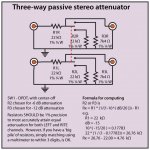
Now, let's get you the values of the 1/8 W./1% tolerance metal film (for low noise) resistors to mount inside the RCA plugs. You are constructing resistive voltage dividers. The formula to use is: dB. = 20 log(α), where α is the "gain". For 6 dB. of attenuation, α = 0.5 and 2X 5.1 Kohm resistors are used. A 10 Kohm part and a 1 Kohm part will yield 21 dB. of attenuation.
Applying the resistor color code to the parts in the photo, I get 57 Kohms/2% tolerance. That's definitely tolerable.
Now, let's get you the values of the 1/8 W./1% tolerance metal film (for low noise) resistors to mount inside the RCA plugs. You are constructing resistive voltage dividers. The formula to use is: dB. = 20 log(α), where α is the "gain". For 6 dB. of attenuation, α = 0.5 and 2X 5.1 Kohm resistors are used. A 10 Kohm part and a 1 Kohm part will yield 21 dB. of attenuation.
I have a pair of the 6db version of these collecting dust... Send me 20 quid and I'll drop them in Airmail tomorrow...
Fmod Style Fixed Value Inline Attenuators
Fmod Style Fixed Value Inline Attenuators
Those fancy attenuator plugs do smell of "snake oil".
What you mean they actually sometimes tell us little white lies in the audio industry to make us spend more than we need to 🙂
I have a pair of the 6db version of these collecting dust... Send me 20 quid and I'll drop them in Airmail tomorrow...
Fmod Style Fixed Value Inline Attenuators
Thank you for the offer but not quite sure what my final solution on this is going to be yet.
- Home
- Amplifiers
- Tubes / Valves
- Adding a simple volume control to a 6j1 pre amp / or just something to reduce level