Hi guys,
I got an ICE Power 1000ASP module all hooked up and running but I do not understand how to connect a 3.5mm 12volt trigger to it. I’m trying to get the amplifier to go into a standby mode triggered by my HT Pre.
The ICE Power modules already have this feature implemented however I cannot understand how to connect the 3.5mm 12volt trigger to it.
I have attached a diagram from the B&O manual of how the 12volt trigger is supposed to be connected to the module, could someone please translate it to me into lamers terms and help me get it working.
Your help is very much appreciated, thank you.
Attachments
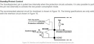
The circuit shown (whose external components I assume you have to add) will put the amp into shutdown when the "Control signal" has sufficient positive voltage applied. This would be the opposite of what you want in a 12v triggering setup (if i understand it correctly). To get a circuit that will default to shutdown/protect and then go active with a constant 12v applied, you could put another pull-down circuit in front of the one shown (that is, replicate R1,R2,BC546B,10k and put it in front of the circuit shown.) Such a circuit would *require* an applied voltage to get out of standby, so a switch might be needed to enable/disable the trigger circuit.
BTW, hooking your 12V trigger straight up to the standby/protect pin (without the pull-down circuit in the manual) might seem to work, but could potentially prevent the amp from activating the protection circuit (during power-up/down ,over-temperature, or over-current conditions).
Corrections to anything stated is appreciated.
If the voltage at the standby pin in 12V, that means that the external circuit shown in the manual is NOT there. You must construct an external circuit to drive the standby pin. (Now someone with more experience with the ICE POWER module might say something like "just connect the trigger to the standby pin through a 5k? ohm resistor, it works fine and won't break anything", but without a threshold voltage spec or knowledge of the detection circuit this is impossible for me to say.) The complexity is that you have to share this pin with the internal shutdown protection circuitry, so you must play nice with it.
Last edited:

I have no hands-on with that particular equipment, but I think I understand the requirements. Without the external circuit, the shutdown pin is pulled high. The BC546B transistor is used as a switch to pull the pin low and enable standby mode. You want to enable standby mode via a trigger from your HT Pre. What trigger signal do you have coming from the HT Pre? Since the transistor is used only as a switch, other types can be used, so it seems to me it makes sense to match it with the signal sent from the HT Pre.
The buffer section is shown as simply an indicator. I don't think I'd bother with it.
The buffer section is shown as simply an indicator. I don't think I'd bother with it.
Hi, thank you for this but I am not exactly sure how the Trig would enable the switch you got in your diagram?
The way i follow your diagram is as follows: the Trig would deliver a 12volt signal, the first resistor would reduce the current a lot, then the transistor would amplify the signal again? or switch the Vcc signal on? (Vcc signal is 12 volts as well btw). then the current would be reduced again by the next resistor and come to the next transistor where it would be applified and supplied to the Suspend pin?
The way i follow your diagram is as follows: the Trig would deliver a 12volt signal, the first resistor would reduce the current a lot, then the transistor would amplify the signal again? or switch the Vcc signal on? (Vcc signal is 12 volts as well btw). then the current would be reduced again by the next resistor and come to the next transistor where it would be applified and supplied to the Suspend pin?
The signal from the trigger is a constant 12Volts, ie when the Pre is on its constantly supplying 12Volts via the headphone type cable, when its off its 0 volts.
I have no hands-on with that particular equipment, but I think I understand the requirements. Without the external circuit, the shutdown pin is pulled high. The BC546B transistor is used as a switch to pull the pin low and enable standby mode. You want to enable standby mode via a trigger from your HT Pre. What trigger signal do you have coming from the HT Pre? Since the transistor is used only as a switch, other types can be used, so it seems to me it makes sense to match it with the signal sent from the HT Pre.
The buffer section is shown as simply an indicator. I don't think I'd bother with it.
andI’m trying to get the amplifier to go into a standby mode triggered by my HT Pre.
I'm confused. What you want is a "remote start", where the amp standby mode is disabled when the HT Pre is turned on. Is that correct?The signal from the trigger is 12Volts, ie when the pre is on its 12Volts, when its off its 0 volts.
Sorry i might have confused people a bit ")
What I'm trying to do is remote start the amp via the Pre. So essentially when i turn the Pre ON I want the Amp to turn ON and when I turn my Pre to Standby, I want my Amp to go into Standby mode as well
When the Pre is ON it outputs a 12volt signal via a trigger cable, its a constant 12volt signal, when the Pre is OFF the signal is 0 volts.
and
I'm confused. What you want is a "remote start", where the amp standby mode is disabled when the HT Pre is turned on. Is that correct?
OK. thune understood from the get-go. I don't suppose you can change the HT Pre trigger so it is 0V when on and 12V when off? Because somewhere that signal needs to be inverted. That's what his circuit does. Neither transistor is used to amplify; they are just switches. Either on or off. And the Vcc in his circuit is a dedicated voltage, ie it is always supplied. So that when the first transistor is on, the second is off. And vice-versa.
I'd like a second opinion for the idea that what may work for you is a normally closed reed relay. Without the trigger the relay pulls the standby pin low, and with the trigger the opened relay disables standby.
Or configure the manual schematic to use a PNP transistor.
I'd like a second opinion for the idea that what may work for you is a normally closed reed relay. Without the trigger the relay pulls the standby pin low, and with the trigger the opened relay disables standby.
Or configure the manual schematic to use a PNP transistor.
Last edited:
Any updates on this?
I am trying to do the same, use a pre-amp to drive the 12V standby operation of an IcePower 250 ASP. Did you succeed in doing this? Did you try running it without the "circuit", with 1 set of circuit and/ or 2 sets of circuits as recommended? Did any of this work? What resistor values did you use?
Would appreciate further guidance on this...
For an amp that requires enable link pulling to ground for enable, follow this link.
Anaview AMS0100-2300 build
The LED state indicator is a nice feature: omit the 2nd & 3rd FETs if not required.
No signal - amp off.
Trigger signal (say 5 to 12v) - Amp on.
Anaview AMS0100-2300 build
The LED state indicator is a nice feature: omit the 2nd & 3rd FETs if not required.
No signal - amp off.
Trigger signal (say 5 to 12v) - Amp on.
If you have 12 volt DC when the pre is on, where is the problem to use a relay? You prevent all kind of trouble like ground noise and have no galvanic connection to the amp.
Cheap as well and build on a small universal PCB,together with pull down resistor, solid and reliable.
Cheap as well and build on a small universal PCB,together with pull down resistor, solid and reliable.
If you have 12 volt DC when the pre is on, where is the problem to use a relay? You prevent all kind of trouble like ground noise and have no galvanic connection to the amp.
Cheap as well and build on a small universal PCB,together with pull down resistor, solid and reliable.
So would something like this work:
DC5/12V 1 Channel Relay Module Opto Isolated board for Arduino and MCU projects | eBay
; with the following connections on the relay:
+ COM: GND from amp (Pin 6 on P2 Connector)
+ NC: Standby/protect (Pin 2 on P2 Connector)
+ CH1: Positive from 12VDC remote trigger on preamp
+ VERF: Negative (ground) from 12VDC remote trigger on preamp
+ DC+: Positive from external constant 12VDC supply
+ DC-: Negative from external constant 12VDC supply
: and no other components in the signal path (between relay and amp on the COM and/or NC connections)? The idea being that the Standby and GND pins are shorted ("pulled to ground"?) when the relay is NOT triggered by the 12VDC from the preamp.
Does anyone know if the 12.8VDC AUX power supply output on the ASP modules (Pins 3 and 5 on P1 connector) is live even when the amp is put into Standby as per above? If so, this could be used to power the relay via DC+ and DC- itself, negating the need for an external 12VDC PSU.
ASP datasheet: https://www.parts-express.com/pedoc...asp-class-d-amp-module-1x1000w-data-sheet.pdf
There are all kinds of unexpensive relay boards, with as many chanels as you like. Any relay can used with it´s opening or closing contacts.
For example
5V 2/4/8/16 Kanal Relay Board Modul Optokoppler LED ARM AIP | eBay
A board comparable to your 6 GBP relay is 1€ to your doorstep. Look what an 8-way is.
You get ripped off!
If you don´t insist on buying in GB from some Chinese crook, buy in China from the same guy and pay 20% of the UK price, including postage. For the time you stay in the EU, you have to pay no taxes (none at all!) or custom fees for your orders, as long as you stay under 20€. There also is a tollerance of 5 €, that usualy gets trough because the tax amont does not make sense. Keep in mind, this is including postage.
So, as long as you order under 24,95€, you are legal and tax free. If you need more, make separate orders on different days.
I know that this truth is fairly unknown and UK-dealers for years have warned about non existant taxes.
The majority of Brit´s does not know, that there are no taxes at all, if they order from the EU. Your local "buy expensive in GB, because I make more money" fraction has done good work in the past.
PS if you dont get your order, tell PayPal, they instandly return your money, I tested it 3 times.
Last edited:
- Home
- Amplifiers
- Class D
- Adding a 12volt trigger to B&O ICEPower modules