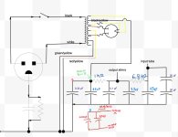
The existing power supply in my audio amplifier lets quite a bit of ripple through producing audible hum. I am planning to add an LC filter to the existing power supply to help filter more of the ripple. I have included a schematic of the power supply with notes showing what I plan to do. After running a simulation in PSUD2 this should greatly reduce the ripple on the B+. The issue is that there is not room left in the amp chassis for this new LC filter. I am planning to mount the new LC filter in its’ own chassis and connect it to the existing power supply using this cable, making it as short as possible. The cable will be for points A, B, and GND shown in the schematic.
Does anyone see an issue with this?
Thank You for your help
Does anyone see an issue with this?
Thank You for your help
Attachments
If you block the ripple, then you also increase the impedance of the supply at low audio frequencies.
It might be worth simulating the rail voltages with various audio frequencies?
You're creating an LC network which will have resonances.
The impedance of the transformer at audio frequencies might be 'not simple'.
I'm not suggesting you are wrong, just that this can be more complex and subtle than meets the eye.
There may be some value in having your inductor lossy at HF, if the real issue is HF noise with a 50Hz repetition rate.
I'm happy for people to explain all this is wrong, many of us are here to learn!
That's a pretty fancy power cable. Probably overkill. 15AWG would be able to handle huge currents. Check the DC voltage rating of the cable.
The main purpose of power supply filters is to remove AC components so only DC is left. Amplifier stages will also have local decoupling capacitors to keep the power clean. AC noise in the power supply will appear in the amplifier output to varying degrees, depending on its topology.
What needs to be looked at is the power supply's behavior when faced with transient current demands. PSUD2 can be used to analyze this.
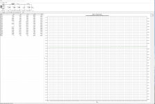
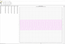
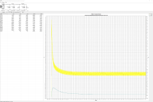
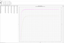
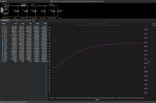
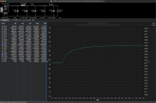
Here are a few screenshots from PSUD2 showing the V-i1, V-i2, i-R1, i-R2, & B+ ripple before and after the addition of the LC filter. I am very new to using PSUD2. I am not sure how to look at transient current demands.
Attachments

If you use a constant current sink as the load, there is an option for a stepped load. This allows you to change the current demand after a set time.
Thank You, can you recommend any realistic values. I tried changing from 10ma to 20ma in 2 seconds and there was quite a large voltage drop.If you use a constant current sink as the load, there is an option for a stepped load. This allows you to change the current demand after a set time.
Jayme, The filament heaters are AC. They are on a separate winding of the power transformer. Do you think adding an LC filter will introduce noise. I will keep the choke away from the transformer and tubes.
I think doubling the current output might be a bit extreme, unless you actually expect that in real life. Maybe 10% or 20% increase in current demand.
I don't use the step function, but have found a reference to it on this site: https://www.diyaudio.com/community/threads/psud-2-road-guide.115260/
I don't use the step function, but have found a reference to it on this site: https://www.diyaudio.com/community/threads/psud-2-road-guide.115260/
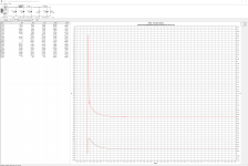
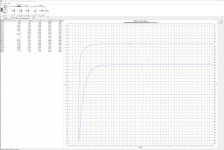
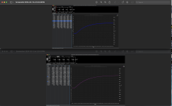
Here are a few screenshots of the step current through the resistors, both before and after the LC filter addition. Does it seem like I am on the right track?
Attachments
-
 Screenshot 2024-02-13 at 5.53.00 PM.png335.2 KB · Views: 50
 -
 Screenshot 2024-02-13 at 5.56.59 PM.png222.1 KB · Views: 46
 -
 Screenshot 2024-02-13 at 5.54.19 PM.png323.3 KB · Views: 54
 -
 Screenshot 2024-02-13 at 5.54.43 PM.png300.4 KB · Views: 52
 -
 Screenshot 2024-02-13 at 5.53.38 PM.png301.3 KB · Views: 49
Can I suggest returning to square one and elaborating on what hum you are experiencing (ie. through a speaker and with just year ears), and how that hum is entering the amplifier. Imho, you may be 'jumping the gun' about the hum being directly due to B+ ripple, and may then be at risk of spending a lot of effort to only find that the hum was due to something else.
Perhaps can you clarify what the amplifier is (eg. schematic), as this will indicate if it is SE or PP or something else, and whether it is triode or UL or pentode, and whether it includes global feedback around the output stage (which would normally attenuate B+ hum). Perhaps also indicate if you were able to measure the ripple voltage, and how you connected the 0V connections of the power supply and output stage and link to chassis. Also were you able to 'measure' the hum to determine if it was mains frequency or 2x that frequency, or something else?
Perhaps can you clarify what the amplifier is (eg. schematic), as this will indicate if it is SE or PP or something else, and whether it is triode or UL or pentode, and whether it includes global feedback around the output stage (which would normally attenuate B+ hum). Perhaps also indicate if you were able to measure the ripple voltage, and how you connected the 0V connections of the power supply and output stage and link to chassis. Also were you able to 'measure' the hum to determine if it was mains frequency or 2x that frequency, or something else?
This is a single ended triode. This amp has no feedback. It is 120Hz hum that I notice from the listening position. The hum is also present with the RCA inputs shorted and the input tubes, and output tubes removed, only the rectifier tube in and speakers connected. The hum is the same with many different rectifier tubes that I have tried, including a solid state rectifier. I have tried various power conditioners and an AC regenerator.
That may indicate coupling from your power transformer to your output transformer, given you observe it with the output stage triode removed (ie. no output transformer primary winding voltage being driven by the triode). The coupling could be just through fields, or could be via the B+ to the top of the output transformer and then through internal coupling to ground.
Is this a diy amp? Is the speaker winding floating, or grounded - does that make a difference to hum level? If you disconnect B+ from the output transformer then does that change hum level? What does the power transformer HT CT connect to (eg. direct to the first filter cap negative terminal) ?
Just trying to appreciate what is happening 🙂
It is not a diy amp. The speaker winding on the output transformers is floating. If I recall correctly I grounded the negatives of the speaker outputs at one point, but it did not make a difference. I have not tried disconnecting the B+ from the output transformer yet. The center taps of the other two transformer windings are connected to ground, the audio ground, not chassis ground.
Thank you for your help. I am going to attempt to take some measurements tomorrow with my digital oscilloscope. I got some 8 ohm, 10 watt resistors to help with that.
Thank you for your help. I am going to attempt to take some measurements tomorrow with my digital oscilloscope. I got some 8 ohm, 10 watt resistors to help with that.
It looks like the ripple on the B+ is causing a signal across the OT primary winding, and then to chassis (through capacitance between the winding and the transformer core) - assuming you only have the output stage triode's anode connecting to that winding end, and you had removed that triode for the test.
Can you confirm you used your normal 8R speaker to 'hear' the hum ?
Do you have a single link from the chassis to the audio ground?
Are you saying the HT transformer centre tap connects to audio ground, but not directly to the first filter cap negative terminal ?
Can you confirm you used your normal 8R speaker to 'hear' the hum ?
Do you have a single link from the chassis to the audio ground?
Are you saying the HT transformer centre tap connects to audio ground, but not directly to the first filter cap negative terminal ?
I used 8 ohm, 98dB sensitive speakers when I hear the hum. I hear it on 87dB speakers, but not as loud.
Yes, there is only one link between the chassis and audio ground, the audio ground is separated from the ground of the plug connector by a 10 ohm resistor and a capacitor in parallel.
The first filter cap negative terminal, and all of the power supply caps negative terminals, are connected to the same audio ground node.
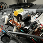
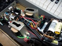
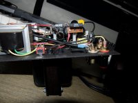
Attached is a photo of the ground node.
I attempted to take measurements today, but it seems that I need a sensitive differential probe for the oscilloscope, or a better DMM.
Yes, there is only one link between the chassis and audio ground, the audio ground is separated from the ground of the plug connector by a 10 ohm resistor and a capacitor in parallel.
The first filter cap negative terminal, and all of the power supply caps negative terminals, are connected to the same audio ground node.
Attached is a photo of the ground node.
I attempted to take measurements today, but it seems that I need a sensitive differential probe for the oscilloscope, or a better DMM.
Attachments
The first filter capacitor has the highest ripple current so the ground point for the amplifier should not be placed there. Locate the audio ground at the negative terminal of the last filter capacitor.
It's hard to see in the photo where the take-off for the audio ground is. Hopefully, there is some spacing between the filter capacitor ground connections, so the audio ground can be placed at the negative of the last capacitor. You may have to rearrange the capacitors a bit.
Also, be aware of loop areas formed by current as it flows to and from components. Keep the supply and return wires close together and twisted if possible. Loops formed by wires act as antennae which can transmit/pickup hum and noise.
The take off for the audio ground is connected via the black wire running above the yellow cap in the photo. That yellow cap and the black cap below it are the first filter caps. They are in parallel before the first resistor. The negative of these two caps are connected directly to the audio ground take off, on the left.
Should I move the audio ground take off wire to the point where that Sprague Atom cap connects, on the right ? This is the negative of the last filter cap.
Thank You
Should I move the audio ground take off wire to the point where that Sprague Atom cap connects, on the right ? This is the negative of the last filter cap.
Thank You
Ripple voltage on a B+ rail may not be easy to measure. Some DMM's autorange to the B+ DC level and don't allow separate AC measurement at low range, and some scopes have issues. A common technique is to use a DC isolation capacitor in series with any scope probe or meter, although even that requires caution to allow that capacitor to charge to B+ dc voltage without transient stress on the scope or meter. Also without the output stage operating, the load current would be relatively small compared to levels one may expect.
I've used a soundcard to measure ripple on B+, and that method requires similar caution to avoid DC from the soundcard input, as well as attenuation of AC voltage, but does provide much higher resolution of low ripple voltage and frequency, as most scopes only provide 8-bit resolution, and some DMMs have only say a 600mVac FS.
The negative terminal of the first filter cap is the noisiest point of a 0V bus, so preferably only the CT connection goes directly to that point, and the link to chassis is made further along the 0V bus (such as at the signal input end of the bus). What do you mean by 'audio ground take off' ? There may be more than one 0V take-offs along a 0V bus, which go to different stages and to a signal input socket. A schematic/sketch of the take-off's and the circuit stages (such as the output stage cathode) is needed to better appreciate what you have.
- Home
- Amplifiers
- Power Supplies
- Add LC Filter / Choke