Can't help with that specific question but be aware of fakes, particularly for devices like the OPA604 and dual OPA2604 as these have I believe been discontinued. Always always buy from official sources.
The circuit configuration of the Adcom suggests that opamps with low input bias current (so FET) are needed in some areas such the opamp the volume pot feeds into due to the direct coupling. Get that wrong and you could end up with noisy pots as you rotate them.
“Noisy pots.”
Besides searching for a better sound, this has been an issue with this one 565 since day one. I even sent it up to ECB (? electronic shop in NJ) for testing. I’ve done signal tracing on it, checked voltages at all test points noted on schematic, even ran it by Chris Hoppe who suggested there was a bias voltage on the volume pot.
Funny, I can clean it (TCE spray, even tried some DEOXIT cleaner/lube), pot’s quiet for a while, a few days, weeks,then all of a sudden, down around zero volume “GRETSCHETA CRUMCHETA POP” which will, eventually, worsen.
That’s another thing leading to changing the IC’s in the gain circuit. The 134’s made it worse, the 604’s (allegedly Burr-Brown TI mfr from Mouser I bought as they were just discontinuing them) too.
I plugged in some Sparkos labs 3601’s last week and not only did the soundstage improve immensely, I had a week of quiet volume control.
Then last night, before turning everything off, I turned the volume down to zero and “click-pop.”
Crap.
Funny thing about that input bias measurement. The TI 604 is rated in PICOamperes (5 or so, IIRC), while the Sparkos 3601 is rated in MICROamperes, but you’d think that’s STILL quiet compared to the original units (which may have been causing the same problem).
For my NEXT project, I’m going to open up both units, side by side and test every circuit and see what’s different.
Thanks.
“Noisy pots.”
Yes. This for example. If the opamp were something like a NE5532 which has a high input bias current then that current (which can be as high as 800na according to the data sheet) flows out of the input pin and via the pot wiper to ground. 800na or 0.8uA may not sound much but it will develop 40 millivolts across a 50k resistor. Any voltage on pin 3 of IC202 will be amplified by the gain of the complete subcircuit so if you can measure a voltage that changes on pin 5 of IC204 for example as you turn the volume control then you have a problem.
DC current flowing in pot wipers is a major cause of noise although of course a pot can just be worn and noisy in its own right.
If this were a FET opamp (and maybe it is) then the bias current is to all practical intents and purposes zero (a few pico amps).
@Mooly
Thanks for this.
I am getting exactly 23 mV at pin 5 on either opamp 204 or its complement. This decreases as volume control increases, to about 1.5 mV.
I’m hard-pressed to find any source for this in either circuit as it is affecting BOTH circuits.
All other voltages so far as I can trace them from power supply forward, every test point indicated on the factory schematics are accurate enough (18V at TIP outputs, 15V at LM78/79)
I’ve even replaced the ICs (202 circuit) with original/OEM, no difference (pot was noisy when I got the unit a couple years ago).
If I spray with TCE/deoxit, it gets quiet for a bit, noise comes back in a few weeks.
Is this just a bad pot, or is there something else I should be looking at?
Thanks again.
It may well be the pot as the main cause, it is a real possibility.
The small DC offset you measure sounds to me like the opamp is a standard bjt type (ordinary transistor input and not FET). If the IC's are easy to swap you could try a FET device for IC202 as a test to see if it helps. Something like an OPA134. The single is the OPA134, data sheet below is the dual version.
https://www.ti.com/product/OPA2134
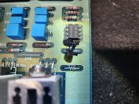
The pot should be replaceable from what I see in pictures. It looks like an ALPS
The small DC offset you measure sounds to me like the opamp is a standard bjt type (ordinary transistor input and not FET). If the IC's are easy to swap you could try a FET device for IC202 as a test to see if it helps. Something like an OPA134. The single is the OPA134, data sheet below is the dual version.
https://www.ti.com/product/OPA2134
The pot should be replaceable from what I see in pictures. It looks like an ALPS
Adcom semiconductor equivalents are discussed in the thread https://www.diyaudio.com/community/threads/adcom-opamp-semiconductor-replacements.339904/
Adcom 1A = LT1010
Adcom 6A = LT1056
Adcom 1A = LT1010
Adcom 6A = LT1056

That's interesting because the LT1056 is a FET opamp (and coincidently the model I use most in LTspice simulations) and interesting because a FET opamp would not give such a change in DC offset as the source impedance (volume control) resistance changes.
I still think a known good FET opamp should be tried.
I still think a known good FET opamp should be tried.
I have that semiconductor replacement cheatsheet from way back when.
I started off with stock, OEM LT1056 opamps, pots were noisy THEN. Chris Hoppe tells me he’s never had a problem with cleaning a pot, suggested I measure offset. I did that.
BEFORE fooling around with anything else, I recapped the board. High-quality Nichicon for power section *(bumping up the 6800 mF to 8200 mF power caps), new TIP110/115 transistors (one, I don’t recall which, HAD blown with only a few volts output), then replaced the voltage regulators with SPARKOS discrete units. ALL voltages are correct. I left R908 alone initially, then changed it to 12.1k for the OPA134AP’s, changed back for all other opamps).
I changed the gain section opamps from LT1056 to OPA134, then OPA604, NOW I‘m using SPARKOS labs 3601s and enjoy the sound, the improvement in reproduction, soundstage, very much. I’m going to stick with the SPARKOS units.
SPARKOS, however, operates a current bias in the milliamp range, 15mA IIRC (I mentioned this earlier in the thread, or maybe it’s the other one), while the OEM TEXAS INSTRUMENTS 604/2604s (I bought last year from Mouser.com) operate in the PICO amp range. I don’t know what the LT1056 units did, but again, the pots were already noisy.
https://sparkoslabs.com/wp-content/uploads/2018/03/SS3601_SS3602.pdf
My NEXT step is to go ahead and replace the pot with a dual 50k ALPS unit and cut out the tone control circuit - I don’t use it anyway.
I just wanted to rule OUT any other circuitry as the source of the bias voltage on output (yes, measureable on all three outputs, although lower on lab/norm vs bypass which is HIGHER, 23mV quiescent).
Hope this clarifies some stuff.
Hello
Well it's been a very trying time around here over the last week and a half with all the weather and helping out my friends and family. Haven't had much time to fiddle with the preamp much until yesterday.
So I knew sooner or later knowing me I would screw something up and did, but I have to say that I am getting just a tiny bit better with the schematics. Not great or I wouldn't have screwed up. Now I'm starting to get a little frustrated with myself.
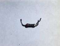
On checking the ICs I must have touched the wrong pin and burnt up a resistor. While I'm at it, I'm just going to replace a couple ICs, 401 and 402. 401 seems to be the one that is giving different readings. It's a chance I'm willing to take.
Reading through the rest of your all post It's just over my head in understanding. Sorry.
You people are great, and I so appreciate every ounce and patience you've given me.
Well it's been a very trying time around here over the last week and a half with all the weather and helping out my friends and family. Haven't had much time to fiddle with the preamp much until yesterday.
So I knew sooner or later knowing me I would screw something up and did, but I have to say that I am getting just a tiny bit better with the schematics. Not great or I wouldn't have screwed up. Now I'm starting to get a little frustrated with myself.
On checking the ICs I must have touched the wrong pin and burnt up a resistor. While I'm at it, I'm just going to replace a couple ICs, 401 and 402. 401 seems to be the one that is giving different readings. It's a chance I'm willing to take.
Reading through the rest of your all post It's just over my head in understanding. Sorry.
You people are great, and I so appreciate every ounce and patience you've given me.
Attachments
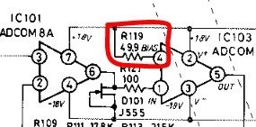
Are you saying you have burnt the 49.9 ohm (it looks to be written as 49.9 anyway)?
If you accidently shorted pin 4 to pin 3 then you placed 36 volts (the total supply of both rails added together) across the resistor. That would smoke it 😀
It is an unusual value as well.
If you accidently shorted pin 4 to pin 3 then you placed 36 volts (the total supply of both rails added together) across the resistor. That would smoke it 😀
It is an unusual value as well.
Are you saying you have burnt the 49.9 ohm (it looks to be written as 49.9 anyway)?
If you accidently shorted pin 4 to pin 3 then you placed 36 volts (the total supply of both rails added together) across the resistor. That would smoke it 😀
It is an unusual value as well.
LOL!
I just did that the other day - TWICE. On IC 205. Despite using insulated needle-point probes for my DVM and while wearing 4 diopter magnifiers. BIG spark. Tone controls still work, sounds fine.
WHEW!
IC 401/402 are for tape out (circuits A and B are identical), and are either OPA 2134 or 2604 (or OEM LT1057).
IF you substitute an OPA 2134 IC for the OEM chip, you need to replace R908 with a 12.1k 1% (or better) 1/4 watt resistor to lower the rail voltage. The OEM 7A dual opamp (or OPA 604 or Sparkos, or Burson, etc substitute) can run at a higher voltage.
Easily done 🙂
(the OPA134 series are fine on -/+18v according to the data sheet and in fact (again data sheet as source) show lower thd on the higher rail voltage)
(the OPA134 series are fine on -/+18v according to the data sheet and in fact (again data sheet as source) show lower thd on the higher rail voltage)
Well, THAT’s interesting.Easily done 🙂
(the OPA134 series are fine on -/+18v according to the data sheet and in fact (again data sheet as source) show lower thd on the higher rail voltage)
I was parroting the suggestions from another post (rodriguez? Bigsky?) in changing the rail voltage.
I’ve got a lot to learn yet. Thanks.
Mikerodrig27 is not Big Sky Audio!BTW, a question for the opamp gurus here.
Everything routes through IC's 205 and 206.
Big Sky Audio's (Mikerodrig27) recommendations for "updating" this preamp only mentioned replacing the gain control chips, IC 201/202, with OPA 134/604, etc.
Has anyone atually replaced 205/206 with similar opamps?
ADCOM 7A is a rebranded LT1057.
The R908 change is for early production GFA-565s only as they had higher voltage rails.IF you substitute an OPA 2134 IC for the OEM chip, you need to replace R908 with a 12.1k 1% (or better) 1/4 watt resistor to lower the rail voltage. The OEM 7A dual opamp (or OPA 604 or Sparkos, or Burson, etc substitute) can run at a higher voltage.
I must have made an impression 😱Mikerodrig27 is not Big Sky Audio!
ADCOM 7A is a rebranded LT1057.
Thank you for jumping back in at DIYaudio. I have enjoyed benefitting from your writeups.
Well after my first resistor order got lost then had to reorder it finely came, but more bad news. After putting it in then turning on the power, the new one started smoking. Now i'm getting really frustrated. This was R119 resistor. My question now is when I was checking IC103 and shorted the R119 out, could I have shorted the inside of the IC to cause my second resistor to go bad?
- Home
- Source & Line
- Analog Line Level
- Adcom GFP 565 OP-Amp help