I've looked to all the threads about the Adcom GFA-585 Lim Ed (is there also a non limited edition by the way?) and I'm pleased and concerned with all the information about this amp.
I can buy one for 500 Euro's but the guy already admits that it makes noises over the speakers when it's cold but it disappears after the amp is warmed up. He first said that was normal with all Adcoms but when I said it was probably dued to leaking caps, even before I read these Threads, he said that that could be fixed by a technician of course.
How big is the chance that I have to perform all the things mentioned here like for instance washing the PCB's after desoldering all the caps and minipots. Is there a chance that I just could replace those "longlife" Elna caps and get away with it or are the noises directly related to abrasive capfluid spilled over the coppertraces on the board?
How good is this amp on Acoustat 2 + 2 electrostatics or paralelled Sixes?
Thanks in advance.
I've replaced thousands of caps in the last few years and nearly half of them simply dried out and didn't leak. The others leaked various amounts, usually a 'mist' around the cap. It often has an unpleasant 'fish' smell when unsoldering. I usually use MG Chemicals flux remover to lean off the leakage. A small number of times the acid will destroy the copper trace which I rebuild with wire wrap wire for the small traces and something more substantial for the power traces.
Remember the acid leak is conductive as it's one of the 'plates' when it's in the capacitor. A more substantial cleaning would not hurt. We've done this with a kitchen dishwasher with excellent results followed by a pass in a food dehydrator of 17 hours at 40-45 C.
It's certainly possible the noise is from the acid residue and because it eats copper, it's best to clean it off. As djk said, give it the full treatment.
G²
Thanks for the replies.
You'll both probably right that there are no shortcuts here.
I'm not a real technician by far but I did manage to repair a Levinson ML-3 and a pair of Thresholds SA/1, with help from this forum of course ;-), so I must be able to pull this of.
Have to find the Dutch substituts for 'UltraCleaner' and Slimgreen to clean the boards.
Will replace all electrolytics on the driverboards with Panasonic FM or FC series and the IC101 'ADCOM 2A' with a OP97.
What is a good quality opamp as put forward by one of the designers of this amp. Vendorrelated?
Never had a Adcom before. Can it be regarded as a affordable 'highend' product? I suppose it was manufactured in the States and not only designed there as with the former Marantz gear in the seventies.
I make píctures, when I get the amp, from before and after.
Greetings
Apart from the leaking electrolytic caps on the driverboards there 's also one 160V/47uF electrolytic cap on each Output PCB. Should I replace them to?
For the driverboards I'm planning to use the Panasonic AM series but they go "only" to 100V.
How about the Panasonic EE series for the 160V on the outputboards?
A friend of mine who designs the Prima Luna tube amps advised me to use the AM series for the Krell KRS-2 preamp overhaul I performed.
The OP97 Walter Jung advised for replacing the ADCOM 2A (LT1012) Servo IC is from Analog Devices.
Basically there are two types the OP97EPZ that costs approx. 10 USD a piece and the OP97FPZ that's only 4 USD. Checked the specsheets and they differ on these specs mainly:
Input Offset Voltage is lower for the 'E' version
OP97EPZ typical: 10 uV, maximum: 60 uV
OP97FPZ typical: 30 uV, maximum: 75 uV
IOS is for both 30 pA
The originalLT1012 has even lower values:
VOS: 8 uV and IOS: 15 pA.
Maybe that should point to the OP97EPZ for a substitute.
Do not know how important that is but maybe someone can comment on this.
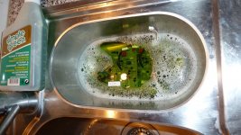
Driverboards take a bath
I got the GFA-585
Left channel more then 1 Volt dc the other fluctuating between - 20mv and plus 20 mv.
When I entered the room were the amp was playing I immediately could smell that nasty fishy odour.
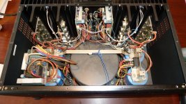
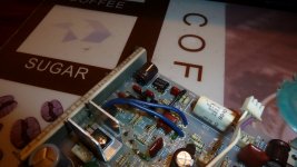
At home I started immediately to make notes off all the connections at the boards. One strange "diy" light blue cable (no not the optional fan one) was attached to both boards in a T from R101 at the Leftchannel Audio Input and R186 of the Righttchannel Audio Input the soldered together and isolated with adhesivetape you can see on top of the toriodal and both the running to Connection 7 at the Right NPN board (this is connected with thick black wire to the minus post of one of the large can capacitors. Total amaeuristic job probably ment to keep the thing stable after the serious damage at the leftboard.
The three Elna 'longlife' caps are definitely leaking and corroding the leftboard.
The servo IC 101 was had some of it legs corroding and two resistors (not the fusible 10 ohm ones) were burned out and open (R206 & R208, 1.21 kohms 1/4 Watt)
It's amazing the amp played at all.
The right board was already been taken care of with a possible easy cleaning and cheap electrolytes.
I cleaned boath boards by letting them bathing in a hot 1 to 5 Simple Green solution. After that I dried them with a blower.
Then I cleaned leftboard again by sparying Simple Green directly on the board and cleaning it with a toothbrush especially on the corroded spots.
I ordered new caps, new pair of servo IC's and two new Bourns 3339P-1-101L trimmers. And the Rightboard the original 4.7 uf 100 Volts DC blocking filmcap was substituted with another one so I will repalce them both with WIMA filmcaps.
I have a nice Variac with a Volt and ammometer on it so after I installed all the parts I will softstart it first. In the Servicemanual it states that I have to shorten the Inrushcurrent resistor R506. Doed that I just have to solder a thick wire between it's poles and I can use the Variac?
Robert
I got the GFA-585
Left channel more then 1 Volt dc the other fluctuating between - 20mv and plus 20 mv.
When I entered the room were the amp was playing I immediately could smell that nasty fishy odour.
At home I started immediately to make notes off all the connections at the boards. One strange "diy" light blue cable (no not the optional fan one) was attached to both boards in a T from R101 at the Leftchannel Audio Input and R186 of the Righttchannel Audio Input the soldered together and isolated with adhesivetape you can see on top of the toriodal and both the running to Connection 7 at the Right NPN board (this is connected with thick black wire to the minus post of one of the large can capacitors. Total amaeuristic job probably ment to keep the thing stable after the serious damage at the leftboard.
The three Elna 'longlife' caps are definitely leaking and corroding the leftboard.
The servo IC 101 was had some of it legs corroding and two resistors (not the fusible 10 ohm ones) were burned out and open (R206 & R208, 1.21 kohms 1/4 Watt)
It's amazing the amp played at all.
The right board was already been taken care of with a possible easy cleaning and cheap electrolytes.
I cleaned boath boards by letting them bathing in a hot 1 to 5 Simple Green solution. After that I dried them with a blower.
Then I cleaned leftboard again by sparying Simple Green directly on the board and cleaning it with a toothbrush especially on the corroded spots.
I ordered new caps, new pair of servo IC's and two new Bourns 3339P-1-101L trimmers. And the Rightboard the original 4.7 uf 100 Volts DC blocking filmcap was substituted with another one so I will repalce them both with WIMA filmcaps.
I have a nice Variac with a Volt and ammometer on it so after I installed all the parts I will softstart it first. In the Servicemanual it states that I have to shorten the Inrushcurrent resistor R506. Doed that I just have to solder a thick wire between it's poles and I can use the Variac?
Robert
Attachments

Last edited:
"there 's also one 160V/47uF electrolytic cap on each Output PCB. Should I replace them to?"
Power ssupply bypass cap, affects the tightness of the bass.
Power ssupply bypass cap, affects the tightness of the bass.
Well, soldered all new components on the inputboards, had to substitute one of the the 10 Ohm fusible resistors on the leftboard as well (R116) and both 10 Ohm fusible resistors on the right board.
Checked all the connections to and from the boards shorted R506 on the AC inputboard and connected the amp to a Variac.
Connected a MM between test points TP301 and TP 401 at both Left outputboards (NPN & PNP) as described in the Service Manual in the biasprocedure.
Switched on the amp and started to turn the dial of the Variac.
After 100 Volts the Relay kicks in (Amp is a 220/240 Volts AC model) and from the MM I get readings that are way to high 100 mV and rising. I cannot do anything about with the biastrimmer R125. When I turn this variable resistor to 0 the MM readings are still to high and I can hear the Toriod humming. So there'd got to be a short somewhere on that Left inputboard.
When I open bot left railfuses and I repeat these steps with the Right inputboard I get no reading at all between TP351 and TP451. That implies and open connection (another fused resistor maybe).
I'm pretty back to zero, have no real glue how to proceed.
Doublechecked all the connections of course.
For the leftchannel maybe a fried Q120 that's in the biascircuit
For the rightchannel one of the resistors in the biasnetwork?
The amp played when I bought it although with lots of DC at the left channel.
Any suggestions/help
- Status
- Not open for further replies.
- Home
- Amplifiers
- Solid State
- Adcom GFA-585 Lim Ed