Any stray continuity between heatsink and collectors of output transistors and drivers? The heatsinks aren't super flat and sometimes a thermal pad can bite through.
You can also try and swap the output module left-to-right. Then you'll know for sure if the problem is in the input board or output section.
You can also try and swap the output module left-to-right. Then you'll know for sure if the problem is in the input board or output secti
I thought about that, but I'm hesitant to go monkeying around with the channel that works. I may have to though, hopefully I'll have time to work on it tonight.
Gary
I replaced Q107, that's not the problem either.
Going to focus on the heat sink again, I've checked everything on the input board.
Going to focus on the heat sink again, I've checked everything on the input board.
If I disconnect the output from the input board and measure the voltage at the output to ground, would I still see the +1.6V and the -1.6V?
Or do I need to install the two 1k ohm resistors like you show to check the board with?
I disconnected it and got +-87V.
Trying to figure out if the output board is messing with the bias voltages.
Gary
Or do I need to install the two 1k ohm resistors like you show to check the board with?
I disconnected it and got +-87V.
Trying to figure out if the output board is messing with the bias voltages.
Gary
I disconnected the input board from the output board, installed the 2 1k Ohm resistors as outlined in the instructions and provided the feedback.
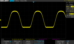
Below is what I'm getting from the input board;

Looks like in all my trouble shooting, I killed something, maybe Q108?
On a positive note the bias voltages look good!
So I'm thinking my original problem is still on the output board.
Below is what I'm getting from the input board;

Looks like in all my trouble shooting, I killed something, maybe Q108?
On a positive note the bias voltages look good!
So I'm thinking my original problem is still on the output board.
Replaced Q108, and that's not the problem, same waveform.
Any ideas Chris? I'm not sure where to go next on the input board.
Gary
Any ideas Chris? I'm not sure where to go next on the input board.
Gary
No other diodes except the 'flybacks' and I check both of them.Any zener or other diodes on the output stage (excluding the flyback diodes to rails)?
I remembered this morning that I still had the output wire connected to the output stage. So I disconnected it and it was better.... for awhile and then it went back to the same waveform. Not sure what would cause that.
Could it be the matched pair Q101 & Q102? They are the only ones I haven't replaced. I did check them.
Another new item is the distortion LED is coming on now.
Gary
Could it be the matched pair Q101 & Q102? They are the only ones I haven't replaced. I did check them.
Another new item is the distortion LED is coming on now.
Gary
- Home
- Amplifiers
- Solid State
- Adcom GFA-555 MKII, Need help with left channel Distortion