Please recomend sampling ADC, DAC pc card with possibility to disable input and output digital filters and any other calculation of signal.
Range 0 Hz - 192 kHz. Minimum 16 bit resolution.
Purpose is exact mesurement of AC/DC signal.
Range 0 Hz - 192 kHz. Minimum 16 bit resolution.
Purpose is exact mesurement of AC/DC signal.
Purpose is exact mesurement of AC/DC signal.
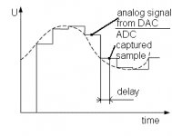
Then let's focus on this. To exactly sample/measure signals we have to avoid aliasing, or else the waveform will suffer very serious distortion in the presence of out-of-band signals. So low-pass filtering is an inherent need for what you're trying to achieve. Digital filters are much better suited for anti-aliasing, due to the high filter order required here. That's why about any contemporary audio ADC involves digital low-pass filters, and it doesn't seem a good idea to me to bypass them...
Samuel
Problem is that analog and digital filters shift phase and amplitude in nonlinear manner. Then it is not possible to reconstruct original wave from DAC to ADC conversion.
I need send signal to speaker throught DAC and then i need to acquire signal throught ADC of speaker real exact amplitude in exact time.
If i set correct sampling rate of DAC and ADC with the same clock source then i do not need filters. I must only set exact delay between DAC sampling step and ADC sampling step to obtain amplitude of "still state" of DAC conversion.
Attachments
Problem is that analog and digital filters shift phase and amplitude in nonlinear manner.
I don't understand the issue--a good digital filter has no appreciable phase and amplitude deviation in the audio frequency range (particularly if you're doing acoustic measurements--the errors of the DAC/ADC will by several orders of magnitude below the effects you're measuring!). There is some group delay (usually a few ms), but you can easily compensate this in software.
If I set correct sampling rate of DAC and ADC with the same clock source then I do not need filters.
Why not? Aliasing will still occur, and the prevalent sigma-delta architecture still needs downsampling filters...
Samuel
That shows a certain misunderstanding concering the nature of correctly designed sampling systems (Analog or digital it matters not), you might want to review some modulation theory.
What are you actually trying to do? What problem are you trying to investigate?
A data aquesition card from national instruments or someone whould give you what you seem to think you want, but I am fairly sure it is the wrong answer to whatever you are actually trying to do.
The anti aliasing/reconstruction filters are not optional if you want a DAC or ADC to actually work in terms of reproducing the band limited signal accurately, your signal labelled 'analog signal from dac' is really nothing of the sort, the analog signal starts when you apply the reconstruction filter.
Almost all modern converters are delta sigma devices that use short word length converters run at high multiples of the 'sampling rate' together with feedback and digital interpolation/decimation filters to do the job.
Regards, Dan.
... There is some group delay (usually a few ms), but you can easily compensate this in software.
Group delay is not acceptable. All frequencies must be presented in correct phase as original.
I done some measurements. With active filters is not possible to fight with different group delay for different frequencies.
... your signal labelled 'analog signal from dac' is really nothing of the sort, the analog signal starts when you apply the reconstruction filter.
Ideal reconstruction is possible only with big hardware update, in future 🙂.
We will need to multiply sampling speed and sampling resolution. Analog "staircase" step on output DAC side will be lesser than value of last bit of input signal to reconstruct.
Example: 16bit 48 kHz signal will be rendered only digitally by real 32bit and 2304 kHz sampling. That will be nice. But now it is not possible and i need to bypass filters.
Purpose is digitally control amplitude of loudspeaker to reduce his THD.
Something like in attachment but with a little bit different principle.
Attachments
The referenced patent is for feedforward correction.
If you want to do that, the delay is irrelevant. You'd have the original signal in digital format, run it through the DSP, apply correction and then send it out to the DAC & speaker.
If, what you want to do, is actually closed loop feedback you will ALWAYS have delay whether you use filtersd or not. Google 'latency'.
jan
Yes, constant delay of all frequencies is irelevant. It will be set easily.
But group delay vary with concrete frequency.
In my principle are 2 stages only. First is calibration only. And second is only playing "calibrated" signal with no feedback. Therefore no feedback with low latency is needed.
But group delay vary with concrete frequency.
In my principle are 2 stages only. First is calibration only. And second is only playing "calibrated" signal with no feedback. Therefore no feedback with low latency is needed.
There is measurement. Up wave is original and sampled bottom.
Dominant distortion is done by DAC`s and ADC`s digital filter.
For signal chain between DAC and ADC is used 7 cm wire only, no other parts.
It is modified Asus Xonar Essence ST card.
Sampling is 192 kHz, original signal is 1920 Hz 1:1 square.
Dominant distortion is done by DAC`s and ADC`s digital filter.
For signal chain between DAC and ADC is used 7 cm wire only, no other parts.
It is modified Asus Xonar Essence ST card.
Sampling is 192 kHz, original signal is 1920 Hz 1:1 square.
Attachments
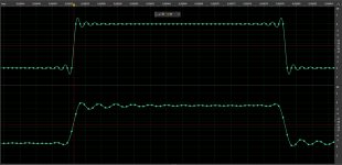
I don't see anything from this picture besides the effect from a bit of additional linear-phase low-pass filtering. The ringing is actually already present in the "original" waveform, as the interpolation of your software shows; that the samples happen to lie all at the zero-crossings of the ringing is just a degenerated case because the square-wave is synchronous to the sampling rate. I think you're trying to change the laws of physics, which is not a promising thing to do... Using a higher sampling rate will mitigate the effect, but not eliminate it.
Samuel
Samuel
I don't see anything from this picture besides the effect from a bit of additional linear-phase low-pass filtering. The ringing is actually already present in the "original" waveform, as the interpolation of your software shows;
You understand exactly. Low-pass filtering is that enemy which i want to eliminate.
And yes, ringing in original signal is software interpolation for bandwidth 96 kHz with low- pass filter. It is only for user`s imagination of sinus wave.
I found ADC audio chip with possibility to bypass digital filters. It is PCM4222 from Texas Instruments.
I know of 16 bit ADC and DAC parts running in at well over 100MSamples/second (Linear Tech do some, as do TI), but you would be looking at an FPGA to handle the data stream that would result which is what I am doing for a cartesian loop transmitter project.
No way to get that into a PC and back out with acceptable latency for this, but a DSP running your math on a sample by sample basis in interrupt contxt could possibly do it.
I think you have major stability problems with applying sufficient feedback to be useful to a real transducer, where the S domain dehaviour is complex and not strictly LTI.
Be careful generating digital square waves, just because you can do it in the Z domain with zero rise and fall time does not make such a set of samples look like a square wave in the continious time domain, your square wave needs to be band limited in the digital domain as well, most easily done by generating as sum of sines up to nyquest limit.
Regards, Dan.
Uff dmills, it is too much science info to my brain in one post 🙂.
I used square signal only for control of signal chain quality.
Square signal with good selected frequency does analyze of DC and AC posibility of devices from one "picture". Horizontal line does DC stability check and vertical line does settling time and slew rate check.
I found next ADC with posibility to disable internal digital filter: ADS1274EVM-PDK
- Status
- Not open for further replies.
- Home
- Design & Build
- Equipment & Tools
- ADC and DAC sampling pc card with possibility to disable digital filters