At this point, I'd be inclined to build up a second copy of the same pc board and see how it works.
If the new board has the same problem, either it's a circuit design error or a problem with the board.
If the new board has the same problem, either it's a circuit design error or a problem with the board.
Last edited:
At this point, I'd be inclined to build up a second copy of the board and see how it works.
If the new board has the same problem, either it's a circuit design error or a problem with the board.
I forgot to say: I made two boards... Same components, same circuit, assembled by JLPCB. One in each speaker box. The problem is the same in both. BUT, I made some mods oriented by this thread on one of them and the distortion now take more time to appear.
Maybe the solution are close.
Ok, I tried... Before C28 has no DC. I'll bypass. Ty.
I put a 100k resistor after the C27 and it made no difference.
I'm getting more crazy about this problem
100K C27 to ground or in series with C27?
How long do you need to leave it powered down for it to recover? Thinking it may be worth waiting until distortion starts getting bad and then power down and short the pins together of the DC blocking caps that are in the signal chain to dissipate any charge and then power up and see if it clears the distortion for a while, if it does then it would imply that the caps are charging and offsetting the signal.
How long do you need to leave it powered down for it to recover? Thinking it may be worth waiting until distortion starts getting bad and then power down and short the pins together of the DC blocking caps that are in the signal chain to dissipate any charge and then power up and see if it clears the distortion for a while, if it does then it would imply that the caps are charging and offsetting the signal.
Hello. I need about 2~3 seconds. Almost instantly... Any suggest?
Member
Joined 2018
Hi icarovps,
Also you need to ...
- reverse C24 polarity.
- Tie-down U3B pin5 to GND with resistor or Jump the W1.
Also you need to ...
- reverse C24 polarity.
- Tie-down U3B pin5 to GND with resistor or Jump the W1.
Hello. I need about 2~3 seconds. Almost instantly... Any suggest?
Slow for distortion to rise but dissipates fast after switch off, odd one, first I would try what CyberPit suggests, do you have a scope? If not then soundcard and Room Eq Wizard's scope signal generator or an old pair of cheap earbuds with a 10K+ resistor in series can be used to follow the signal path.
Hi icarovps,
Also you need to ...
- reverse C24 polarity.
- Tie-down U3B pin5 to GND with resistor or Jump the W1.
YOU ROCK!!!!!!!! The second tip solved my problem... Many months of headache... Maybe 4 or 5 months searching wtf happened in my design.
CyberPit, can you explain to me why this happened? And why after putting 100k on GND did it work?
Slow for distortion to rise but dissipates fast after switch off, odd one, first I would try what CyberPit suggests, do you have a scope? If not then soundcard and Room Eq Wizard's scope signal generator or an old pair of cheap earbuds with a 10K+ resistor in series can be used to follow the signal path.
Thank you too man... I saw many problems on my design after your tips.
You asked me at the beginning if my dc blocking caps had path to ground, but i hadn't thought about AD, but DA. My bad
Member
Joined 2018
Hi icarovps,YOU ROCK!!!!!!!! The second tip solved my problem... Many months of headache... Maybe 4 or 5 months searching wtf happened in my design.
CyberPit, can you explain to me why this happened? And why after putting 100k on GND did it work?
Congratulations!

The U3B operating point will follow the non-inverted input voltage. If there's no tie-down resistor, that will follow the Op-amp's input offset conditions. It will drift a bit some temperatures, supply voltages or leak current of DC-blocking Caps. Biasing input terminal fixes operating point stays stable GND voltage forever.
CyberPit
Hi icarovps,
Congratulations!
The U3B operating point will follow the non-inverted input voltage. If there's no tie-down resistor, that will follow the Op-amp's input offset conditions. It will drift a bit some temperatures, supply voltages or leak current of DC-blocking Caps. Biasing input terminal fixes operating point stays stable GND voltage forever.
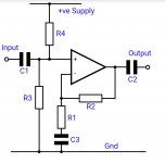
I looked and saw that are several non-inverter configurations. One of them is mine, but there is one that left me with doubts...
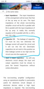
My configuration is with symmetric source (+/- 15v). However, I saw that the non-inverting configuration I am using should be for simple sources (just +15v), because of capacitor C3 (C36 on my board).
Should I remove it? Or swap? What can he do badly on my circuit?
Attachments
Member
Joined 2018
Hi icarovps,

BTW, In your design case, my suggestions are ...
If you want to change the design to the single power supply, maybe my FreeDSP Classic SMD A/B (plus-2) design will help you some...
CyberPit
Your suggested circuit will amplify the noise contained in positive power rail. So I like to do this way.My configuration is with symmetric source (+/- 15v). However, I saw that the non-inverting configuration I am using should be for simple sources (just +15v), because of capacitor C3 (C36 on my board).
Should I remove it? Or swap? What can he do badly on my circuit?
BTW, In your design case, my suggestions are ...
- Replace C27 with jumper wire.
- Change C36 Polar-Ele-Cap to Non-polarity or Bi-Polarity Ele-Cap .
- C24
- C39
- C48
- C58
- C67
- C11
- C47
- C56
- C66
If you want to change the design to the single power supply, maybe my FreeDSP Classic SMD A/B (plus-2) design will help you some...
CyberPit
Hi icarovps,
Your suggested circuit will amplify the noise contained in positive power rail. So I like to do this way.
BTW, In your design case, my suggestions are ...
Please remember rotating following caps...
- Replace C27 with jumper wire.
- Change C36 Polar-Ele-Cap to Non-polarity or Bi-Polarity Ele-Cap .
Following caps will be undefined the right directions..
- C24
- C39
- C48
- C58
- C67
Easiest way to define the polarity of of Ele-Caps is measure the each voltage with multi-meter(DC-range)😀
- C11
- C47
- C56
- C66
If you want to change the design to the single power supply, maybe my FreeDSP Classic SMD A/B (plus-2) design will help you some...
CyberPit
Perfect! I already rotated the caps... This was the first thing I did. I'll check and define the polarity of the DAC caps...
One more (and last, I swear) thing ... (I'm so excited because my circuit worked that I can't stop)
I'll work in a second version of this circuit, but I think with symmetric source is more easy and don't need a bias (I still find it complicated to work with bias)
The C36... 100uF is enough? Or too much? I tried calculate the equivalent resistance in the R32-R34-R33-R35 node to put in your formula to calculate the BW, for then calculate the capacitor, but I failed.
And the 100k resistor to GND (after C27), I can remove it, right?
Thanks for your patience... For real.
Member
Joined 2018
Hello again icarovps,
The simulation result says 2.2uF for C36 is minimum. 10uF is more than enough, 100uF is too much.The C36... 100uF is enough? Or too much? I tried calculate the equivalent resistance in the R32-R34-R33-R35 node to put in your formula to calculate the BW, for then calculate the capacitor, but I failed.
Yes, you can remove tie-down 100K resistor. It's not need anymore if you jump the C27.And the 100k resistor to GND (after C27), I can remove it, right?
Attachments
- Home
- Source & Line
- Digital Line Level
- ADAU1701 audio completely distorted after a while