ZXTN2018 has "851" as laser mark on the sot-23 package.
The sot-23 can dissipate slightly less. Noisewise, they were
identical in my tests.
The sot-23 can dissipate slightly less. Noisewise, they were
identical in my tests.
If you want to measure the noise of very low noise references and supplies, you may want to use a design with much lower noise.
I built an amplifier based on the ideas in this thread:
Low noise preamplifier
With a bipolar transistor on the input, I achieved an input noise of around 0.27nV/sqrtHz at flat band above 1 kHz. I used a ZTX851.
With a FET version, using BF862, I got an input noise of around 0.84nV/sqrtHz, so almost 10dB worse.
The input noise is now around 1nV/sqrtHz. Most of that comes from the resistor.
So the 50 ohm resistor adds a "terrible" amount of noise. The two 22 ohm resistors you have on the inputs will also add quite a lot of noise.
I didn't use any resistors for input protection. I just clamped the input to ground with a couple of 1A rectifier diodes, after AC coupling of course.
Well,
IMHO the input amp must be differential, otherwise any RF pickups on the GND connections will be the reusult
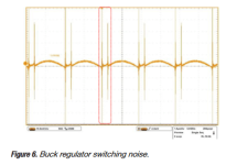
As good TI resource as "Simplifying Power Architectures, With Low-Noise Power Devices" shows the issues very clearly:
Some figures of this document
- Low freq. noise; as low freq. LNA required
- Switching noise, caused by the ADC/DAC power(s) and other parts; as high freq. LNA required at xxMHz or even xxxMhz.
New 12 Bit DSO & averaging & ERES to16bit on xxMHz may help to show this switching noise.
Some prefer any shunt regulators, but it is unknown how they react on capacity/resistor switching load, beside of simulations. Compared to the most used LT3042.
Attachments

Differential amps are a bad idea for low noise - you get two sources of voltage noise instead of one.
@Mark Tillotson:
Hmm, as I expect the differential as the final noise/signal... while connecting any DSO or alike will induce any RF signal into GND connections.
So 3 connections as: [+] [-] and GND as any DSO differential probes as LeCroy AP034
Hmm, as I expect the differential as the final noise/signal... while connecting any DSO or alike will induce any RF signal into GND connections.
So 3 connections as: [+] [-] and GND as any DSO differential probes as LeCroy AP034
I built a low noise amp som years ago to measure power supplies. I cheated, and used a Geoformer to get something like .1 Ohm EIN. The Geoformer has response to below .1 Hz, limited HF but thats less important.
SSM2019 has excellent E(in) of 1nV/RtHz, 1pA/RtHz but high input bias current.Differential amps are a bad idea for low noise - you get two sources of voltage noise instead of one.
But a single ended version with the same input devices would be 0.7nV/√Hz... Differential pairs put two noise sources in series. For ultimate in low voltage noise you parallel devices only, like the classic ZTX851/951 push-pull pair.
CMRR deteriorates severely as frequency rises, many, if not most of the differential amplifiers have a poor CMRR at high audio frequencies, let alone at RF. A good RF enclosure and good grounding/shielding yields much better results than a conventional diff amp at rejecting RF. Of course, perhaps more sophisticated diff amp solutions by TI or AD can work wonders by rejecting RF, but a homebrewed LNA is most likely to have an atrocious CMRR at RF. Plus, as others have mentioned, diff amps produce more noise than single ended.Well,
IMHO the input amp must be differential, otherwise any RF pickups on the GND connections will be the reusult
As good TI resource as "Simplifying Power Architectures, With Low-Noise Power Devices" shows the issues very clearly:
Some figures of this document
- Low freq. noise; as low freq. LNA required
- Switching noise, caused by the ADC/DAC power(s) and other parts; as high freq. LNA required at xxMHz or even xxxMhz.
New 12 Bit DSO & averaging & ERES to16bit on xxMHz may help to show this switching noise.
Some prefer any shunt regulators, but it is unknown how they react on capacity/resistor switching load, beside of simulations. Compared to the most used LT3042.
Time for an update. I ended up building the AD8428 LNA as I found a couple of chips in the stash. It is not the last word in performance, but I wanted to share some preliminary findings in case anyone else chooses to go down this road. All measurements are taken with shorted inputs, and with a -66dB offset to obtain RTI noise readings, and a single AD8428 (no parallel parts) and +/-6.8V rails after regulation. Other settings are visible in the screenshot.
The first round of measurements was disspointing. Unfortunately I did not save the graph, but the 1/f corner was around 100Hz-- much higher than the datasheet 1/f corner. I suspect this was the input bias current working into the 500k input bias resistors, and generating a noise voltage at the input. I ended up replacing the input cap with a 25uF Kemet film cap, and the bias resistors were dropped to 50k. This creates a lowpass with -3dB at 0.13Hz, and brough the corner down to about 30Hz.
I then performed a few other modifications and tested to see how they impacted the measured response. The input ferrites are Fair-Rite 2512061027Y1s. Replacing them with a short didn't impact the noise performance.

I tried increasing the capacitance across the LT3045/3094's Rset by piggybacking 4.7uF caps. The results are a bit too close to say 3x 4.7uF (blue trace, topmost) performed worse than 1x (red trace, bottom), but it did not measure better. These are 1206 Murata GJ8s, X7R, 50V. Perhaps the leakage begins to matter when you have that many, or maybe the flux that crept between the parts created a new leakage path. Perhaps the AD part's PSRR is good enough that none of this matters?
Next up, I cleaned the boards with IPA. This also gave a small, but measurable improvement (tan trace, middle in below graph). Another interesting observation is that cleaning the boards reduced the output voltage offset by a few microvolts, suggesting that there was indeed a leakage path that got cleared up. The topmost blue trace in the below graph shows the APx515 SE input shorted-- so if nothing else, this will be useful for audio band measurements.

Finally, shorting the input coupling caps (such that the in-amp's + and - in are effectively shorted) brings the 1/f corner to about 4Hz (purple bottommost trace). This seems a bit too good to be true? Certainly better than the datasheet. I'm sure I'm missing something, but I'll continue to explore the bias current noise theory as well as any leakage effects the BAV199 input protection may be contributing.
The first round of measurements was disspointing. Unfortunately I did not save the graph, but the 1/f corner was around 100Hz-- much higher than the datasheet 1/f corner. I suspect this was the input bias current working into the 500k input bias resistors, and generating a noise voltage at the input. I ended up replacing the input cap with a 25uF Kemet film cap, and the bias resistors were dropped to 50k. This creates a lowpass with -3dB at 0.13Hz, and brough the corner down to about 30Hz.
I then performed a few other modifications and tested to see how they impacted the measured response. The input ferrites are Fair-Rite 2512061027Y1s. Replacing them with a short didn't impact the noise performance.
I tried increasing the capacitance across the LT3045/3094's Rset by piggybacking 4.7uF caps. The results are a bit too close to say 3x 4.7uF (blue trace, topmost) performed worse than 1x (red trace, bottom), but it did not measure better. These are 1206 Murata GJ8s, X7R, 50V. Perhaps the leakage begins to matter when you have that many, or maybe the flux that crept between the parts created a new leakage path. Perhaps the AD part's PSRR is good enough that none of this matters?
Next up, I cleaned the boards with IPA. This also gave a small, but measurable improvement (tan trace, middle in below graph). Another interesting observation is that cleaning the boards reduced the output voltage offset by a few microvolts, suggesting that there was indeed a leakage path that got cleared up. The topmost blue trace in the below graph shows the APx515 SE input shorted-- so if nothing else, this will be useful for audio band measurements.
Finally, shorting the input coupling caps (such that the in-amp's + and - in are effectively shorted) brings the 1/f corner to about 4Hz (purple bottommost trace). This seems a bit too good to be true? Certainly better than the datasheet. I'm sure I'm missing something, but I'll continue to explore the bias current noise theory as well as any leakage effects the BAV199 input protection may be contributing.
Nice, to see how it goes on. As I deal with RF AD8129 and important as you have high 60Hz related harmonics...
1) Just BOX the amplifier and may shield internally to get ride of RF & hum
2) for the LT30xx ref may use 22u tantalum or similar
3) there are better once than BAV133 as 1PS70SB8x
Hp
1) Just BOX the amplifier and may shield internally to get ride of RF & hum
2) for the LT30xx ref may use 22u tantalum or similar
3) there are better once than BAV133 as 1PS70SB8x
Hp
And not to forget to measure the CMRR 😀
and one more thing, as your 10u input cap looks very large. Consider a Rubycon-Polymer 😀
and one more thing, as your 10u input cap looks very large. Consider a Rubycon-Polymer 😀
The current noise 1/f corner is around 75Hz, which roughly matches those graphs - for a source impedance above 800 ohms or so the AD8428 is current-noise dominated.Unfortunately I did not save the graph, but the 1/f corner was around 100Hz-- much higher than the datasheet 1/f corner. I suspect this was the input bias current working into the 500k input bias resistors, and generating a noise voltage at the input.

I don't know exactly what is your source impedance, but the datasheet shows 1.3 nV/rtHz and 1.5 pA/rtHz spectral densities for voltage and current noise, respectively. This implies that the optimum source impedance is roughly 867 ohms. I don't know if you are considering your source impedance into account. From a quick glance at your schematic, when you say 500k input bias resistors, I am assuming you mean the parallel combination of those 1M resistors. Without knowing exactly what you are connecting to the input of your amp and what its source impedance is, there is not much that can be argued.
I still think that a single ended input with paralleled low-noise BJTs is a better way to go if you do not need differential inputs. The THAT 300 series of transistor arrays are an excellent alternative. Have a look at this short design note: https://thatcorp.com/datashts/dn109.pdf
I still think that a single ended input with paralleled low-noise BJTs is a better way to go if you do not need differential inputs. The THAT 300 series of transistor arrays are an excellent alternative. Have a look at this short design note: https://thatcorp.com/datashts/dn109.pdf
for a source impedance above 800 ohms or so the AD8428 is current-noise dominated.
Indeed, I think this is the insight that I was missing. I replaced the input cap with 2000uF (Nichicon VK electrolytics, nothing fancy) and the bias resistor with 1k, and suddenly the noise is very close to that of the DC coupled measurement. The settling time is atrocious, at least 15 minutes before I can take a repeatable measurement down to 0.5 Hz.This implies that the optimum source impedance is roughly 867 ohms. I don't know if you are considering your source impedance into account.
I realize I probably come across as a stubborn with wanting to stick with the AD8428 despite great recommendations for a discrete or composite amp. The main goal of the project was to measure the output noise of an LT3045 from 0.1Hz to 10Hz with different voltage references on the set pin. My assumption was that I wouldn't do better than the LTC6655 (80nV/sqrt(Hz)) and that my source impedance was basically zero. So really, resolution to even 1nV was not necessary. and the AD chip seemed like a good-enough turnkey solution for someone who has never taken low noise or low frequency measurements.
I made a couple of mistakes. The idea with using a differential amp is that this would save me the input coupling caps. It didn't cross my mind that 3.3V multiplied by a gain of 2000 could be problematic. 🙂 It also didn't occur to me that the AD8428 would not actually see the low source Z unless I used big enough caps. The aversion to big caps on the input is really an aversion to worrying about finding a low leakage cap in large values.
I picked up a bag of ZTX851/951s and will be taking a closer look at the composite amp. Thanks again to all for the tips!
Hi, interesting work! This may have been a preliminary schematic, but I noticed C1 & C2 do not have a charging path. A resistor to ground prior to these capacitors will prevent them from suddenly charging when a source is connected with the preamp turned on. If it’s been addressed already, disregard!My implementation is very close to that of the datasheet. C1/C2 are input coupling caps in a footprint that accommodates up to 25uF (Kemet C4AQLBU5250M12K). With 1M resistors to bias the in-amp's inputs, fc can be made as low as 0.0064Hz.
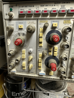
In my LNA's I provide a low impedance path to short the amplifier input to ground, draining C(in) -- it's via a 3 pin 0.100" Molex header and SPDT switch. The Tektronix differential amplifiers shown below both have this type of input protection with push-buttons.
It's helpful to be able to switch 60 ohms onto the input -- you have a 1nV/Rt Hz reference for sanity testing. 390R will give a 2.5nV/Rt Hz reference.
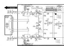
Also include a screenshot of the 5A26N input protection.
It's helpful to be able to switch 60 ohms onto the input -- you have a 1nV/Rt Hz reference for sanity testing. 390R will give a 2.5nV/Rt Hz reference.
Also include a screenshot of the 5A26N input protection.
Attachments
Indeed, I think this is the insight that I was missing. I replaced the input cap with 2000uF (Nichicon VK electrolytics, nothing fancy) and the bias resistor with 1k, and suddenly the noise is very close to that of the DC coupled measurement. The settling time is atrocious, at least 15 minutes before I can take a repeatable measurement down to 0.5 Hz.
The may a simple switch to pre-charge the cap as others used to do.
So currently I see now 3 required LNA's:
1 - for 1/f
2 - for audio range
3- for RF range as may starting at 1...10kHz
I measured using my AD8129 as about 25 dB gain and digital power showed any surprises.
The pita on this AD8129 is the lower BW as you set for mor gain. Also getting CMRR down to 40dB at 100Mhz.
So locking for any better OPAMP, as it looks there aren't any, even not newer AD8129 substitutions. 😳
You didn't mention anything about the source impedance, and source impedance is critical. To measure low-frequency noise from a low source impedance the LT1028 is a good choice. The 1/f noise spec is great.
Well, currently, I am ONLY on the RF trail.
As mentioned:
The pita on this AD8129 is the lower BW as you set for more gain. Also getting CMRR down to 40dB at 100Mhz.
So locking for any better OPAMP, as it looks there aren't any, even not newer AD8129 substitutions
More or less up to some xx MHz its OK, but above...
May I lower the AD8129 gain for higher BW and add at the inputs as for (+) & (-) fast OPAMP's to get the required gain back.
BUT, the issue as CMRR remains on the AD8129. That's why I am looking for any newer & better OPAMP than AD8129 with better CMRR.
- Home
- Design & Build
- Equipment & Tools
- AD8428 Low Noise Preamplifier