I'm interested in measuring the voltage noise of different voltage references, particularly at low frequencies, and found myself quickly running into the limitations of my audio analyzer. So, I need a preamp.
There are plenty of designs available already. To name a few, many by community members--
https://www.bartola.co.uk/valves/2014/01/18/the-noise-inspector/
http://www.janascard.cz/aHome.html
https://www.diyaudio.com/community/...card-for-audio-and-noise-measurements.342721/
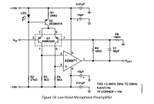
I liked the idea of maintaining battery operation, allowing the circuit to float. I also wanted the option of DC coupling the inputs if needed as well as AC coupling with a very low (<0.01Hz) cutoff frequency using film caps. This led me to consider the AD8428 instrumentation preamp.
The input-referrenced voltage noise is not quite as good as some of the above designs, but it's quite low and has a much lower 1/f corner than most op amps, as a $20 op amp should. ADI had the audacity to recommend paralleling these to obtain nanovolt sensitivity. The notion of parallelling $80 worth of op amps is appalling. I'd like to try it.

My implementation is very close to that of the datasheet. C1/C2 are input coupling caps in a footprint that accommodates up to 25uF (Kemet C4AQLBU5250M12K). With 1M resistors to bias the in-amp's inputs, fc can be made as low as 0.0064Hz. A pair of jumpers allow for DC coupling on the inputs, or connections to external capacitors to boost the input capacitance further. TI went as high as 5100uF in one app note on measuring LDO noise, so I assume there's no harm to going big here.
F1-2, R1-2, and C3-5 provide some protection from EMI. R1-R2 does double duty and also provides protection from large differential input voltages. There is minimal protection against input voltages beyond the rails (R1/R2 provides modest current limiting for the internal diodes), so care must be taken when using DC coupling. If anyone has suggestions for which ferrite chips to use, ADI's datasheet was a bit light on details. 🙂

There's no great way to parallel these parts without mucking up the layout. Instead, each pin connects to a header, and daughterboards can be stacked vertically-- just like we used to do with TDA1543s. This also makes it entirely reasonable to test with just one in-amp installed, and makes the filter pins easily accessible should the need ever arise.

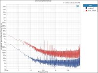
For the power supply-- I purchased a pair of EBL 9V Li-Ion batteries and was very disappointed by how noisy they are. I'm getting around 32uVRMS with a DC-90kHz bandwidth. The AD8428's 120dB+ of PSRR can no doubt handle it, but I'll sleep better at night knowing the battery is regulated. An LT3045/LT3094 pair is at least 40x quieter and provides a lower supply impedance, and makes it possible to run the preamp off of the mains if need be. I attached a measurement of the EBL battery (6F22 Li-Ion 600mAh) for reference.
The implementation is fairly standard. Looking at the positive regulator, the battery is filtered by F3/C6. R7 sets the current limit, and R6 sets the output voltage to 7V (as the Li-Ion is closer to 8V than 9V on a full charge). C4 is the 4.7uF reference filter cap (Cset), and this board uses the recommended Murata GJ8 parts. The output cap is a kelvin-connected Panasonic SP-cap.

The board is <10cm in both directions, so should be inexpensive from the usual suppliers.
Any feedback on the design (or suggestions for potential enclosures!) would be greatly appreciated. I'm happy to make the board files available if anyone thinks it could be of use to them.
There are plenty of designs available already. To name a few, many by community members--
https://www.bartola.co.uk/valves/2014/01/18/the-noise-inspector/
http://www.janascard.cz/aHome.html
https://www.diyaudio.com/community/...card-for-audio-and-noise-measurements.342721/
I liked the idea of maintaining battery operation, allowing the circuit to float. I also wanted the option of DC coupling the inputs if needed as well as AC coupling with a very low (<0.01Hz) cutoff frequency using film caps. This led me to consider the AD8428 instrumentation preamp.
The input-referrenced voltage noise is not quite as good as some of the above designs, but it's quite low and has a much lower 1/f corner than most op amps, as a $20 op amp should. ADI had the audacity to recommend paralleling these to obtain nanovolt sensitivity. The notion of parallelling $80 worth of op amps is appalling. I'd like to try it.
My implementation is very close to that of the datasheet. C1/C2 are input coupling caps in a footprint that accommodates up to 25uF (Kemet C4AQLBU5250M12K). With 1M resistors to bias the in-amp's inputs, fc can be made as low as 0.0064Hz. A pair of jumpers allow for DC coupling on the inputs, or connections to external capacitors to boost the input capacitance further. TI went as high as 5100uF in one app note on measuring LDO noise, so I assume there's no harm to going big here.
F1-2, R1-2, and C3-5 provide some protection from EMI. R1-R2 does double duty and also provides protection from large differential input voltages. There is minimal protection against input voltages beyond the rails (R1/R2 provides modest current limiting for the internal diodes), so care must be taken when using DC coupling. If anyone has suggestions for which ferrite chips to use, ADI's datasheet was a bit light on details. 🙂
There's no great way to parallel these parts without mucking up the layout. Instead, each pin connects to a header, and daughterboards can be stacked vertically-- just like we used to do with TDA1543s. This also makes it entirely reasonable to test with just one in-amp installed, and makes the filter pins easily accessible should the need ever arise.
For the power supply-- I purchased a pair of EBL 9V Li-Ion batteries and was very disappointed by how noisy they are. I'm getting around 32uVRMS with a DC-90kHz bandwidth. The AD8428's 120dB+ of PSRR can no doubt handle it, but I'll sleep better at night knowing the battery is regulated. An LT3045/LT3094 pair is at least 40x quieter and provides a lower supply impedance, and makes it possible to run the preamp off of the mains if need be. I attached a measurement of the EBL battery (6F22 Li-Ion 600mAh) for reference.
The implementation is fairly standard. Looking at the positive regulator, the battery is filtered by F3/C6. R7 sets the current limit, and R6 sets the output voltage to 7V (as the Li-Ion is closer to 8V than 9V on a full charge). C4 is the 4.7uF reference filter cap (Cset), and this board uses the recommended Murata GJ8 parts. The output cap is a kelvin-connected Panasonic SP-cap.
The board is <10cm in both directions, so should be inexpensive from the usual suppliers.
Any feedback on the design (or suggestions for potential enclosures!) would be greatly appreciated. I'm happy to make the board files available if anyone thinks it could be of use to them.
Attachments
Last edited:

If you want to measure the noise of very low noise references and supplies, you may want to use a design with much lower noise.
I built an amplifier based on the ideas in this thread:
Low noise preamplifier
With a bipolar transistor on the input, I achieved an input noise of around 0.27nV/sqrtHz at flat band above 1 kHz. I used a ZTX851.
With a FET version, using BF862, I got an input noise of around 0.84nV/sqrtHz, so almost 10dB worse.
This is the noise measured at the output of the bipolar version, with shorted input:

-120dB = 1uV/sqrtHz at the output = 1nV/sqrtHz at the input with 60dB gain.
This is the output noise of the FET version:

With the bipolar version and 50 ohm on the input:

The input noise is now around 1nV/sqrtHz. Most of that comes from the resistor.
So the 50 ohm resistor adds a "terrible" amount of noise. The two 22 ohm resistors you have on the inputs will also add quite a lot of noise.
I didn't use any resistors for input protection. I just clamped the input to ground with a couple of 1A rectifier diodes, after AC coupling of course.
I built an amplifier based on the ideas in this thread:
Low noise preamplifier
With a bipolar transistor on the input, I achieved an input noise of around 0.27nV/sqrtHz at flat band above 1 kHz. I used a ZTX851.
With a FET version, using BF862, I got an input noise of around 0.84nV/sqrtHz, so almost 10dB worse.
This is the noise measured at the output of the bipolar version, with shorted input:
-120dB = 1uV/sqrtHz at the output = 1nV/sqrtHz at the input with 60dB gain.
This is the output noise of the FET version:
With the bipolar version and 50 ohm on the input:
The input noise is now around 1nV/sqrtHz. Most of that comes from the resistor.
So the 50 ohm resistor adds a "terrible" amount of noise. The two 22 ohm resistors you have on the inputs will also add quite a lot of noise.
I didn't use any resistors for input protection. I just clamped the input to ground with a couple of 1A rectifier diodes, after AC coupling of course.
I would tend to use signal diodes like 1n4148 for such clamping as they have much less capacitance (diode capacitance is very non-linear), so a pair of rectifier diodes might contribute distortion.
That can also be done, but I was mainly interested in the noise in the uV range, so very little AC signal and distortion was not critical. The DC voltage across the diodes is 0V when things have settled.
And I used a 470uF low ESR capacitor on the input before the diodes, so a rather high current may flow when connecting it to a decoupled regulator output.
But if 1N4148 can survive, fine. I haven't tested it though.
And I used a 470uF low ESR capacitor on the input before the diodes, so a rather high current may flow when connecting it to a decoupled regulator output.
But if 1N4148 can survive, fine. I haven't tested it though.
Frankly, I don't believe the battery noise traces.
< http://www.hoffmann-hochfrequenz.de/downloads/NoiseMeasurementsOnChemicalBatteries.pdf >
The stronger than 1/f rise below 50 Hz comes from the 10k * (10*10 uF foil) input,
as Scott saw on the spot.
Li-Ion 16850 was also OK, but I burnt the preamplifier when I searched for an
unexplained 50 pV noise rise @ 1 MHz before taking the final measurement.
Last edited:
You may want to take a look at this webpage https://www.dicks-website.eu/low_noise_amp_part1/part1.html there is a lot of good info there on how to make a relatively simple low noise amp.
In part 3 of that same webpage there are a lot of measured specs for transistors, you can select the one that best suits your application and make a transistor/op-amp hybrid as @JensH suggested.
In my opinion, if you only want an op-amp with no discrete components, the AD797 is virtually unmatched in terms of noise voltage for an op-amp, but it obviously depends on the source impedance you are dealing with. The AD797 has a considerably high current noise, so if you are dealing with large source impedances, you should consider something else. You didn't mention your source impedance, so I am assuming it is low.
Do you really need differential inputs? or can you manage with a single AD797 or a transistor/op-amp hybrid? If you need differential inputs you should consider a Double-Balanced (AKA Cohen) Microphone preamplifier topology. It is basically a two transistor/opamp hybrid which allows for differential inputs and lots of gain.
If you want an integrated solution, you should consider the THAT1580 IC: https://thatcorp.com/that-1580-low-noise-differential-audio-preamplifier-ic/ or the THAT 1510/1512 https://thatcorp.com/that-1510-1512-low-noise-high-performance-audio-preamplifiers/ , both of them have a 1nV/rtHz EIN at 60dB of gain; it really doesn't get much better than that (pun not intended). AFAIK, those ICs are based on the Cohen topology, but they are meant to be used with a low source impedance.
Last edited:
I'm interested in measuring the voltage noise of different voltage references, particularly at low frequencies, and found myself quickly running into the limitations of my audio analyzer. So, I need a preamp.
There are plenty of designs available already. To name a few, many by community members--
https://www.bartola.co.uk/valves/2014/01/18/the-noise-inspector/
http://www.janascard.cz/aHome.html
https://www.diyaudio.com/community/...card-for-audio-and-noise-measurements.342721/
I liked the idea of maintaining battery operation, allowing the circuit to float. I also wanted the option of DC coupling the inputs if needed as well as AC coupling with a very low (<0.01Hz) cutoff frequency using film caps. This led me to consider the AD8428 instrumentation preamp.
Well, interesting, may consider on ADC/DAC (not only on VRef) unknown high speed switching current. So may consider AD8129/AD8130 to get into the unknown as not provided any details (as real current load and shapes) within the AKM/ESS datasheets 😀
So very interesting as an additional high speed preamp for any 12 bit DSO 😀
Hp
Regarding LF noise Cset is the most important capacitor on LT3045/LT3094 and for low LF noise 22uF would be better. Class II ceramics should be avoided for Cset due to microphony.
Last edited:
May some should read and any other TI papers:
Fundamentals of Precision ADC Noise Analysis: Design tips and tricks to reduce noise with delta-sigma ADCs
as a starting point about.... and starting to consider different supplies:
analog (AVDD), digital (DVDD) and the low-voltage modulator supply (LVDD) 🙄
my 2 cents
Hp
Fundamentals of Precision ADC Noise Analysis: Design tips and tricks to reduce noise with delta-sigma ADCs
as a starting point about.... and starting to consider different supplies:
analog (AVDD), digital (DVDD) and the low-voltage modulator supply (LVDD) 🙄
my 2 cents
Hp
Thanks to everyone for the thoughtful replies. Looks like I might not be on the right path after all; apprectiate all the pointers!
This looks fantastic. The VO1263 bias is a very neat trick; do you mind sharing how you adapted it to bias the BJT? I'm imagining you flipped the PV stack of the VO1263 and reduced the base bias resistor to a much lower value, scaling the input cap accordingly (to 470u)? If you have a schematic of what worked for you, I'd love to replicate it.
Thanks for highlighting how much the 22R resistors would degrade the noise performance. I like the idea of big clamps.
Considering that your posts on noise measurements are what got me interested in the topic, this sounds like important feedback. 🙂
The measurements were taken by connecting an EBL battery to the APx515 single ended input using a BNC to alligator clip cable, with the loopback connecting the single ended generator output to the single ended input of the undriven channel. Both channels are DC-coupled with a 90kHz bandwidth. The only loading was the analyzer's 200k input impedance. The measurement is 4 power averages with an FFT length of 1.2M. No particular efforts were made to shield anything. I agree, the white noise seems very high, but perhaps this has something to do with the circuitry associate to building the 9V cell?
The fact that you use 10 pairs of AD4898-2s tells me that a couple of AD8428s probably won't cut it.
I'll be working with low impedance sources. I briefly considered the 797 but was concerned about the 1/f corner being much higher than that of the AD8428. It looks like the low frequency noise contribution will be very similar, and that the AD797 has a lower white noise floor which shifts the 1/f corner to a higher frequency.
With a bipolar transistor on the input, I achieved an input noise of around 0.27nV/sqrtHz at flat band above 1 kHz. I used a ZTX851.
This looks fantastic. The VO1263 bias is a very neat trick; do you mind sharing how you adapted it to bias the BJT? I'm imagining you flipped the PV stack of the VO1263 and reduced the base bias resistor to a much lower value, scaling the input cap accordingly (to 470u)? If you have a schematic of what worked for you, I'd love to replicate it.
Thanks for highlighting how much the 22R resistors would degrade the noise performance. I like the idea of big clamps.
Frankly, I don't believe the battery noise traces.
Considering that your posts on noise measurements are what got me interested in the topic, this sounds like important feedback. 🙂
The measurements were taken by connecting an EBL battery to the APx515 single ended input using a BNC to alligator clip cable, with the loopback connecting the single ended generator output to the single ended input of the undriven channel. Both channels are DC-coupled with a 90kHz bandwidth. The only loading was the analyzer's 200k input impedance. The measurement is 4 power averages with an FFT length of 1.2M. No particular efforts were made to shield anything. I agree, the white noise seems very high, but perhaps this has something to do with the circuitry associate to building the 9V cell?
The fact that you use 10 pairs of AD4898-2s tells me that a couple of AD8428s probably won't cut it.
This is a gold mine. Thanks for the link!You may want to take a look at this webpage https://www.dicks-website.eu/low_noise_amp_part1/part1.html there is a lot of good info there on how to make a relatively simple low noise amp.
The appeal of an op amp design is really only that op amp datasheets have specified noise performance. It's nice to have an easily set gain, but that's something that can always be calibrated down the line.In my opinion, if you only want an op-amp with no discrete components, the AD797 is virtually unmatched in terms of noise voltage for an op-amp, but it obviously depends on the source impedance you are dealing with.
I'll be working with low impedance sources. I briefly considered the 797 but was concerned about the 1/f corner being much higher than that of the AD8428. It looks like the low frequency noise contribution will be very similar, and that the AD797 has a lower white noise floor which shifts the 1/f corner to a higher frequency.
I do not. 🙂 And a discrete/hybrid solution is also fine; I just prefer to avoid overly large capacitors needed to bias some of the discrete designs. Prior to seeing the design that @JensH linked, my fallback would have been the design from the SSM2220 datasheet, attached at the end of the post (with 1k/1R resistors in the feedback network). But if we can do single ended, I won't say no to half the noise.Do you really need differential inputs?
Thanks for catching this! I was counting on the in-amp's PSRR at very low frequencies, but may as well fix the problem at the source.Regarding LF noise Cset is the most important capacitor on LT3045/LT3094 and for low LF noise 22uF would be better. Class II ceramics should be avoided for Cset due to microphony.
Attachments
OPA210 (or OPA2210 for dual) has better 1/f voltage & current noise characteristics than AD8428 but obviously lacks the in-built fixed 2000 gain. You get 5 OPA210s for the price of AD8428.
This looks fantastic. The VO1263 bias is a very neat trick; do you mind sharing how you adapted it to bias the BJT? I'm imagining you flipped the PV stack of the VO1263 and reduced the base bias resistor to a much lower value, scaling the input cap accordingly (to 470u)? If you have a schematic of what worked for you, I'd love to replicate it.
Yes, the trick with the VO1263 is quite neat.
But with a bipolar solution it is actually not needed.
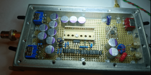
I have attached a schematic of my design.
There are two outputs. One is intended for a single ended output (BNC), intended for connection to an oscilloscope. The other output is a balanced output, where I used an XLR connector. This is intended for connection to an audio analyzer.
The input (BNC) connector is mounted directly on the PCB to keep wires short.
The amplifier runs on a single 9 V battery.
I added a battery monitor, with green light when the battery voltage is OK and red light when it becomes too low.
The design was implemented on a 50x50 mm PCB. And mounted in a small metal box.
Attachments
That "dicks-website" link I provided has a lot of measured data for different transistors, both npn and pnp. You can probably choose one of those that have the lowest base resistance and I am sure you can make an awesome hybrid low-noise amp.The appeal of an op amp design is really only that op amp datasheets have specified noise performance. It's nice to have an easily set gain, but that's something that can always be calibrated down the line.
I've built that ribbon mike preamp from Horowitz/Hill "Art Of Electronics" ed.3.
It is differential, but my version is only single-ended. 16 ZTX851 instead of 64 pcs.
I pay with 10*1000uF input capacitors, but the interesting AC voltages are seldom
centered around 0V DC. I get abt. 75 pV/rtHz voltage noise as promised by AOE3.
Current noise is not so funny, but the voltage noise of a DUT of a few Ohms would
already be stronger than that of the amplifier.
AOE3 has also measurements & results of many transistors.
There is a sot-23 version of the ztx851, something with ???2018
I usually have a switch in the input of my amplfiers that can short it to GND or
to a 60 Ohms resistor. 60 Ohms delivers ~1 nVrtHz at room temperature and by
shorting it you can see the amplifiers absolute own noise. You don't even need
to know the exact gain.
Be careful with that shorting switch when you have the amplifier connected
to a Li cell as a DUT.
Attachments
Last edited:
Interesting - some datasheets I found for my pair show 851 and 951 markings on the package, and the max peak currents are -15A and 20A which agree with the ZTX951/851. The 2018/2027 also show the same markings on the datasheet I think, but the peak currents are lower...
Unfortunately datasheets of these have little data on noise. AOE3 has noise measurements of ZTXN2018/ZXTP2027.
Great suggestion, and very nicely done circuit! I may point out that if you went through the trouble of using that wonderful RF/Microwave-style enclosure, you might as well could've used a proper PCB, but, again, great work.I've built that ribbon mike preamp from Horowitz/Hill "Art Of Electronics" ed.3.
It is differential, but my version is only single-ended. 16 ZTX851 instead of 64 pcs.
I pay with 10*1000uF input capacitors, but the interesting AC voltages are seldom
centered around 0V DC. I get abt. 75 pV/rtHz voltage noise as promised by AOE3.
Current noise is not so funny, but the voltage noise of a DUT of a few Ohms would
already be stronger than that of the amplifier.
AOE3 has also measurements & results of many transistors.
There is a sot-23 version of the ztx851, something with ???2018
I usually have a switch in the input of my amplfiers that can short it to GND or
to a 60 Ohms resistor. 60 Ohms delivers ~1 nVrtHz at room temperature and by
shorting it you can see the amplifiers absolute own noise. You don't even need
to know the exact gain.
Be careful with that shorting switch when you have the amplifier connected
to a Li cell as a DUT.
The 2012 seems to test different from the '951 here: http://www.dicks-website.eu/low_noise_amp_part5/part5.html - whether that's more than device variation is hard to know - perhaps they are different fabs involved?Unfortunately datasheets of these have little data on noise. AOE3 has noise measurements of ZTXN2018/ZXTP2027.
- Home
- Design & Build
- Equipment & Tools
- AD8428 Low Noise Preamplifier