lyyydddkkkk,
I'm curious how the DAC is going. I've been eyeballing the same board.
Sry... for late reply... I was away duo to overloaded 🙂 work!
The DAC is playing very nicely, this kind of DAC absolutely giving very fine music, -I like it better than my non R2R one 🙂
Jesper.
Better than to have no work at all!
Thank you - I actually ordered the board yesterday!
So are you going to feed it with Salas's psu's ? Or do you have another plan ?
Jesper.
I'm going with zener emitter followers and plenty of capacitance. Not well respected, but work so well, so simple.
First step will use V out. Then will likely try a Pass D1 I/V variant. There is something about the sound of warm mosfets......
First step will use V out. Then will likely try a Pass D1 I/V variant. There is something about the sound of warm mosfets......
Then will likely try a Pass D1 I/V variant. There is something about the sound of warm mosfets......
Any link/schm. for this ?
Thanx!
Any link/schm. for this ?
Thanx!
For the life of me i can't find the exact thread I was looking at. but here is a start..
DIY D1 I/V STAGE
the original D1 was designed to follow a BB PCM63 which I believe had twice the Iout of the AD18XXs. There is a thread out there where it was simulated and some R value changes made it run perfectly with 1ma Iout.
....then there is the ZEN I/V
Zen I/V Converter | Pass DIY
Yes PCM63 say's :
And our 1856 is :
Excatly...
Jesper.
FAST (200ns) CURRENT OUTPUT
(±2mA; ±2% max)
And our 1856 is :
Bipolar Range (±30%) ±1.0 mA
Output Impedance (±30%) 1.7 kΩ
Excatly...
Jesper.
SWITCHING between spdif and usb inputs
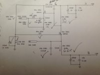
So while still in progress with figuring out which kindoff i/v i will try out, one of my colleges would like to try this DAC with some CD-player with spdif-out; so i bought this cheap spdif to i2s converter.
Quistion is, if it's okay to relay-switch the 4 lines, letting the "i2s-gnd" just pass through.
Anyway look at the attached picture, for better explanation.
The picture shows the spdif to i2s converter, the usb to i2s and the DAC!
Rgds; Jesper.
Attachments

Looks like you're getting pretty brave switching that data around - please let us know how it works out! I personally don't think I could pull it off.
For mine, I chickened out and ended up going with boring 'lousy' 3 terminal regulators fairly well implemented. Everyone knows just how 'bad' that is 🙂
It's that you can't blow it up, and I've been real unlucky lately!
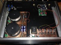
Anyway, I got my board in, and it's running on V out. Using JLsounds I2SoverUSB (recommended for the support alone. Nice guy)
Sounds better than anything I've had here, not that I've had great stuff. Clean, 3 dimensional, quiet, etc. Looking forward to doing the Pass D1 I/V circuit. have amps to build first though 🙂
crappy cell phone pic of incomplete mess...
For mine, I chickened out and ended up going with boring 'lousy' 3 terminal regulators fairly well implemented. Everyone knows just how 'bad' that is 🙂
It's that you can't blow it up, and I've been real unlucky lately!
Anyway, I got my board in, and it's running on V out. Using JLsounds I2SoverUSB (recommended for the support alone. Nice guy)
Sounds better than anything I've had here, not that I've had great stuff. Clean, 3 dimensional, quiet, etc. Looking forward to doing the Pass D1 I/V circuit. have amps to build first though 🙂
crappy cell phone pic of incomplete mess...
Attachments
Last edited:
First, the AD1856 is simply Analog Device's direct replacement for the once popular PCM56 made by Burr-Brown. Second, I didn't notice any mention of whether your DAC is being operated NOS; meaning, without a digital oversampling filter. If it is operated NOS, then member 'Bernhard' has an interesting completely passive I/U solution. No one that I know has more experience with, including having perfromed extensive spectrum analyzer measurements upon, the PCM56 than has Bernhard. A named search of Bernhard on this site will produce many interesting comments, including an elegant passive I/U solution featuring reconstruction filtering, and zero-order-hold-aperture frequency-droop corrective EQ.
Here's a likn to one such diyaudio comment of his: http://www.diyaudio.com/forums/digital-line-level/142514-pcm56k-iv-resistor-value.html#post1806002
Here's a likn to one such diyaudio comment of his: http://www.diyaudio.com/forums/digital-line-level/142514-pcm56k-iv-resistor-value.html#post1806002
Last edited:
Hi Ken,
Honestly, I can't be sure if, or not it is oversampling. The vendor lists it as "AD1856 R2R Isolated nonoversampling NOS Audio DAC with FIFO reclock ". U doubt the JLsounds I2Sover USB can change this (unless increasing sample rate above 44.1 in software accomplishes this?).
I am not a DAC guy and this is my first attempt at something DIY DAC. I'm personally not looking for the end-all of DACS, just something DIY in my system that sounds good to me.
Thanks for the suggestions.
One of my concerns - The DAC chips are currently set up for Vout, will it be necessary to lift some leg before tapping for Iout or simply disconnect ?
Jesper, not trying to destroy your thread - kick me out if you want 🙂
Jesper, not trying to destroy your thread - kick me out if you want 🙂
You are absolutely not destroying anything here !
Regarding the use of Vout or Iot, i am pretty sure that U just choose what you wanna use 🙂
Rgds; Jesper.
That is what I was hoping. both on not destroying anything, and running Iout
Did you find that this board SHOULD have thermal reliefs at the ground plane thru-holes? It put an end to my old Hexacon Magnum station!
Did you find that this board SHOULD have thermal reliefs at the ground plane thru-holes? It put an end to my old Hexacon Magnum station!
Hi Ken,
Honestly, I can't be sure if, or not it is oversampling. The vendor lists it as "AD1856 R2R Isolated nonoversampling NOS Audio DAC with FIFO reclock ". U doubt the JLsounds I2Sover USB can change this (unless increasing sample rate above 44.1 in software accomplishes this?).
Very much sounds as though it's non-oversampling (NOS). Among the implications of this is that unless EQ'd back to flat, the DAC will exhibit an approximately -3dB response droop at 20kHz. The designer may have provided such EQ, or may simply have ignord the droop, which is quite common to do. Unless specifically mentioned in the user manuel, this is hard to say for sure without measurement.
Bernhard's passive I/U incorporates both an analog reconstuction filter and droop EQ circuit, along with a simple resistor I/U. My experience is that simple passive resistor I/U can be extremely clear sounding.
One of my concerns - The DAC chips are currently set up for Vout, will it be necessary to lift some leg before tapping for Iout or simply disconnect?
Likely, yes, followed by a bit of foil trace re-routing (by soldering in short lengths of jumper wire) as well. I do not recommemd making such modifications to your DAC board unless you have PCB modification experience, and know what you are doing. While not at all difficult for an experienced hobbyist, it's easy for an novice to accidentally damage their DAC.
Last edited:
- Status
- Not open for further replies.
- Home
- Source & Line
- Digital Line Level
- AD1856 I/V (I/U) converter