I have been assembling notes here, and on other threads in my attempt to understand amps. My wife is super sensitive to some unknown problem with horns blareing, like good big band, but not live. It is the amp. So, a few questions:
A comment on dislike for current mirrors. Could you elaborate? The Rotel 951 that we find most listenable does not have them, where more "advanced, like my DH-120, B&K 140, HCA 1200 do, all failing her test. A "text book" requirement.
A lot of ideas on bias. I had not heard low output bias as causing bright sound. This is easy to test. Does it apply to L-MOSFTEs as well? Exicon is specific about 110mA, Hafler spec on the Hitachi was 125, but the amp could only do 95 ( fixing that of course). Mr. Curl cautioned me that a lot of the Parasounds were not adjusted correctly, but as mine is very happy on my woofers, I am not pulling it out right now.
IPS bias. This is a tough one if one can't find complete datasheets, like on just about everything. This is a very limited view, but in looking at a couple of parts, you need to pick a trade-off between source impedance and bias current which for them was in the range of .75 to 1.2mA per device. About what Erno picked for my 120. Cordell and Self "routinely" use higher, 1 to 2.5 per device, but with no explanation.
Odd temp: I would be grabbing for a scope to look for parastatic oscillations.
So, The Aragon has a bigger supply and servo. Neither shows much in the way of protection circuits, turn on delay, mute, remote trigger.
A bit of experience I do have: Mod-ing an amp is an easy way to test silicon fuses. If you can't get all the parts or have found suitable substitutes, pick one you can. I was very happy with switching to a HEXFRED rectifier and 4X larger PS caps. Lower noise floor and 8 to 12 lower line harmonics. Testing the limits of my modified supply found, well the limits which cost me a very expensive set of MOSFETS from England. If you can't say "darn" and walk away, pick something else.
Spice is handy, but does not tell all. It took me a week to tame the changes in the DH-120 that were just fine in simulation. I spent all day yesterday doing alternate ccs configurations which the authorities claim to have great effects. Simulation showed very little difference and not always in the direction I expected. My conclusion is the two diode, single transistor is the best performer and the transistor matters more. Hmmm, exactlly the configuration in the Aragon and even the same transistor I wish I had the model for to simulate!
Acurus A250 Schematic
I have a slightly different schematic for the A250 along with the oem sales brosure and performance review if any would like.
I attempted to link it but the files are tool large and I am not sure how to comress them.
I have two of these amps, the first I sent to a repair shop in NY to have dual rectifiers and (4) 23,000 uf caps....I like the sound...the shop did or frankinstin hatch job on the amp though,,,Stuffed it with carpeting foam padding!!!!!!. So I up graded the second myself. worth doing....
Attachments
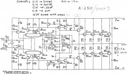
IThe LTP current is set at about 1.8mA, so the VAS standing current is about 3.6ma
Didn't you mean 2 x 3.6mA ?
Jacco, the LTP current sources are biased using 2 diodes and the transistor has a 200 Ohm resistor in the emitter - this gives about 3-3.5mA so 1.5 to 1.8mA per LTP side.
The LTP current is really a matter of choice for the designer and a few tradeoffs have to be made. For low LTP currents (1-3mA), the input transistor bias currents are low, but in order to acheive high slew rates, you need a lot of LTP degeneration (which lowers loop gain), or, you need to look at MIC. With high LTP currents (I bias mine at 5mA per side), you can acheive high slew rates using standard MC or TMC, and if you go for MIC, damn high slew rates. However, the bias currents through the feedback resistors are high causing offsets, so you need to make these quite low in value (which is what I do) and make sure there are no thermal distortion effects due to resistor heating (use a few good quality metal film resistors in parallel).
The VAS standing current by my calculation is about 6-7mA. On my Ovation 250 amp I run the VAS much higher than this (I was taken to task over this by a few of the guys here on the forum!). I used standard Miller compensation on the original design, but now changed to TMC. This Acurus design uses MIC (15pf) and a small Cdom of 10pF, so you can get away with lower LTP currents, though IMO the VAS standing current is too low for a big EF2 like this. On an EF3, I think about 15mA is about right and on an EF2, you will need a bit more.
WRT the compensation design, I would have to put it on a simulator to see what's going on.
The correct output stage bias current is indeed 26mV across the output stage emitter degen resistors, so across a P-N pair, 52mV. So, for 0.33 Ohm resistors, the output current would be 78mA per pair, and by way of example, for 0.22 Ohm resistors, 118mA. If you have 5 pairs of output devices, this soon mounts up and for the last case mentioned above, 5 pairs gives nearly 90watts off standing dissipation (150V total supply voltage). If you are constrained by heatsink ize, then the best option is to increase the emitter degen resistors so that you can lower the bias current - 0.47 Ohms will give about 41W (5 pairs on 150V rails).
I note that the Zobel network seems extraordinarily heavy at 1.5Ohms and 0.22uF. Normally 8-10 Ohms and 0.1uF does an adequate job, and I have to wonder if the designer had some problems with ringing or HF stability - maybe this might explain the shrieking treble some people mention. There is no output coil shown (is it mounted at the speaker terminals perhaps?), but I would think this would help stability.
Anyway - if you can pick these Acurus/Mondial amps up cheap 2nd hand, they make interesting platforms to experiment on. Happy tweaking!
Last edited:
In my opinion, this amp is not worth modding/upgrading. I've owned two and tinkered with both. For what you can get them for used you'd spend as much on mods, not to mention your time.
Build something from scratch.
Interesting comments regarding the Zobel network as I found the amp borderline (un)stable. If one channel or the other is running warmer/hotter than the other, check your bias, if not, I would suspect it's oscillating somewhere. Maybe your speaker cables are acting as an antenna.
Valid comments hags. There are about 10 mods I would do to this amp to raise performance and cost would be about $5. But, of course, it requires time and effort.
Valid comments hags. There are about 10 mods I would do to this amp to raise performance and cost would be about $5. But, of course, it requires time and effort.
Well, as a previous owner of this model amp I can give you my opinion from experience.
I did manage to improve the sound of this amp, it was still not where I wanted it to be, especially when you hit the point of diminishing returns. Like I said, IMO, not worth doing the work.
My time and effort are better spent on other things. You could build any one of a half dozen projects that are current in the solid state forum here and more than likely come out with much better sound.
The DH-220s I've modded, extensively, were more satisfying than my two Acurus amps.
My $.02.
Schematic
Hello, I was wondering do you still have the schematic for a Acurus A200 Amp?
Trying to fix mine.
I haven't posted in quite awhile. I thought maybe someone besides myself could use this.
An externally hosted image should be here but it was not working when we last tested it.
Maybe someone can tell me why these amps are notorious for ear shrieking treble gain.
Hello, I was wondering do you still have the schematic for a Acurus A200 Amp?
Trying to fix mine.
Schematic
Hello I'm a newbie,
I am looking for the schematic for a Acurus A200 Amp.I notice you stated you posted it @ one time. I am trying to fix mine. I read all the comments left. My amp on the left channel heats up starting at the back. I mean really hot only w/ the power connected, I noticed it one day when I was dusting. It plays fine & use it for my rear channel in my system, I don't use it now of coarse. Do you think my amp has drifted that much(bias), I think you & Chamberlain where stating that.
Not a pro, just wondering if any help could be found.
Thanks😕
Acurus A200 amp
Adjusted the bias to the suggested 6-7 mv range. No more left channel heat problem. While I did my A200, I did my A200X3 amp also. Thanks for all the good
info.😀😀😀😀😀😀😀
Adjusted the bias to the suggested 6-7 mv range. No more left channel heat problem. While I did my A200, I did my A200X3 amp also. Thanks for all the good
info.😀😀😀😀😀😀😀
What is MC, TMC, VAS, WRT and MIC?in order to acheive high slew rates, you need a lot of LTP degeneration (which lowers loop gain), or, you need to look at MIC. With high LTP currents (I bias mine at 5mA per side), you can acheive high slew rates using standard MC or TMC, and if you go for MIC
I don't know MIC, but I know the global feedback resistor has a 15pF in parallel to form a zero on the feedback to compensate a pole in the open loop gain. If that is the case, why you can lower the LTP current if you reduce to 10pF?The VAS standing current by my calculation is about 6-7mA. I used standard Miller compensation on the original design, but now changed to TMC. This Acurus design uses MIC (15pf) and a small Cdom of 10pF, so you can get away with lower LTP currents, though IMO the VAS standing current is too low for a big EF2 like this. On an EF3, I think about 15mA is about right and on an EF2, you will need a bit more.
It has to be for stability compensation by introducing a lead lag network.I note that the Zobel network seems extraordinarily heavy at 1.5Ohms and 0.22uF. Normally 8-10 Ohms and 0.1uF does an adequate job, and I have to wonder if the designer had some problems with ringing or HF stability - maybe this might explain the shrieking treble some people mention. There is no output coil shown (is it mounted at the speaker terminals perhaps?), but I would think this would help stability.
I know this is a very old post, but this is a very good post, I see a lot of useful information. I have the older 200X3. It has 330000uF caps for the two rail voltages. This is what I did in the post http://www.diyaudio.com/forums/solid-state/263318-any-way-improve-sound-my-acurus-5.html
It is interesting that you increase the input LTP current. You hear a significant improvement? I am interested in trying this.
Last edited:
In my opinion, this amp is not worth modding/upgrading. I've owned two and tinkered with both. For what you can get them for used you'd spend as much on mods, not to mention your time.
It's all different opinion. For me, I already own the amp, I am not going to buy another one just to modify. This is what I have and I am stuck with it.
I am planning to build a tube power amp, but it takes time, so improving this amp is a stop gap for me to buy time.
I don't think this is a bad amp, it's all relative. You get what you pay. Of cause it's not going to compare with the real high end amp. But it can also be a whole lot worst. So far, I improved the amp a bit and it did not even cost me much. $5 is more like the cost. I am going to try increase the tail current and maybe add an offset adjust to compensate the increase base current of the LTP. That's not going to cost much at all. I can just add extra diode ( 3rd diode) to double the tail current.
- Status
- Not open for further replies.
- Home
- Amplifiers
- Solid State
- Acurus A200 schematic here