"and replace the current mirror through ordinary resistors. "
I see no current mirror, I do see a cascode of the LTP and a CCS.
Making it like the latest version of the Leach is an easy improvement.
I see no current mirror, I do see a cascode of the LTP and a CCS.
Making it like the latest version of the Leach is an easy improvement.
Last edited:
"and replace the current mirror through ordinary resistors. "I see no current mirror, I do see a cascode of the LTP and a CCS.
Making it like the latest version of the Leach is an easy improvement.
Yes, you're right, I had overlooked this.
I have found a couple options for power supply caps and was wondering what you guys might recommend.
1) epcos 22,000 mf 100v $59.0ea. These have really low ESR (5 typ and 10 max @100hz) Ripple current 17a @ 100hz @85 deg or 45a @40 deg. They are almost 3 times the price on Mouser. I would like to up grade to the 33000 mf unit but Digikey does not have them and like mentioned, mouser is too much coin.
2) kendeil K02 22,000 mf 100v. $155 pair. These have an ESR of 10 typ @100hz. Ripple current 16.5a @ 100hz @105 deg or 46.2a @40 deg. Very similar ripple but higher ESR than EPCOS. They are normally 3" base but seller has them in 2.5" which fits factory mount.
3) Kendeil K01 33,000 mf 100v $165 pair. ESR 10 Ripple 23.1 Based on 85c
Is it worth upgrading to larger Mf. I have to change mount but there is room. Can't find the 33000mf Epcos for a good price. Digikey does not list that size. Could by 4 22000 units but is it really necessary. what would I gain?
Mike
got my Epcos caps installed. Just dio fit. Raised the bias as well. Sounds much smoother on top end. Caps that we in it were from 1992. Also bought some Elna Silmic II caps to replace the old input and feed back electrolytics. Haven't installed them yet.
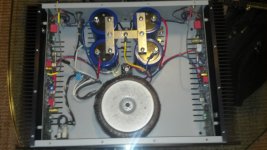
Just for curiosity, I started mocking up a layout in my other A250 using the spare two caps that I just pulled from the 1st a250. I now have 4 22,000 mf caps installed in a very clean setup. The original caps are short enough to stand vertically. I wonder why they didn't do it this way. Very easy to fit all 4 caps in there. Now I just have to figure how to power them from the rectifier. I can double the positive and negative leads I guess or add a second rectifier. The one that comes stock is a 35a diotec.
heres some pics
Attachments

I am quite familiar with this topology. I did a few calculations and the designer seems to be running the front end and VAS stages very 'lean'. The LTP current is set at about 1.8mA, so the VAS standing current is about 3.6ma which is low for a 2EF design. I will need to do some calls, but the UGF might also need some adjustment.
I cannot see the output circuit properly, but it looks like no inductor.
The slew rate is about 100v/us by my reckoning, but I think the ULG frequency will probably be set too high.
If you ask me why this amp may have shrieking treble, I think it's due to sub optimal compensation design (Cdom, LTP degen resistors), low LTP current and low VAS current. The 15pf cap from the VAS to the inverting input also curtails feedback at HF, not helping matters. The designer has used 2 VAS transistors in parallel and here you could imagine a better solution like a beta enhanced VAS to improve both linearity of the VAS and open loop gain of the amplifier.
If the heat sinks are decent (sorry, cannot make this out from the photo), then you may be able to tweak this amp into quite a performer in my view in sonic terms.
Anyway, good luck with your project. 🙂
Last edited:

Not an engineer. If by LTP you mean bias, I have already raised it to 6mv. I have not done anything else other than swap to new PS caps. There is no audible hum or his with patch cords disconnected. I do get hiss with patch cords connected but I know this comes from Acurus act3 pre/pro. I have no bypass caps, no snubbers, no soft recovery diodes. Just stock PS setup. If I don't hear hum, is there any reason to further bolster power supply.
As far as input signal side. All I have are some Elna Silmic II caps to replace to two electrolytics that were already there. No redisgn.
Mike
As far as input signal side. All I have are some Elna Silmic II caps to replace to two electrolytics that were already there. No redisgn.
Mike
Just read this article regarding setting bias and quiescent current. He states it is best set somewhere between 100ma and 150ma. This is measured at the emitter resistors. In our case, we have .5 ohm resistors and 6mv across them. That's only 12ma. A far cry from 100. what gives? Am I applying this info wrong?
Adjusting the Bias Of Your Amp [English]
[FONT=Arial, Helvetica][/FONT]
Adjusting the Bias Of Your Amp [English]
[FONT=Arial, Helvetica][/FONT]
Just read a long article stating that the optimal bias setting is 20-25mv across the emitter resistor. D Self and John Curl state that this was measured to be where distortion is least and that it is the voltage drop across the emitter resistor that is important. This is much higher than the manufacturer states to set this amp at but the experts state that for any EF BJT circuit, this 20-25mv is the ideal setting. Would this high of a voltage be safe to use on this amp given the high rail voltages and .5 ohm resistors? Since we have the schematic and the size of the heat sync specs in this thread, what do you guys think.
25mV would be 29.2W at 73V with 8 outputs.
Try it and see how hot it is after one hour, and just lower if over 145°F.
Try it and see how hot it is after one hour, and just lower if over 145°F.
the a250 runs at 85v so I guess a little more watts consumed but I will slowly raise it up over a couple days to see how it goes. I have a laser temp probe here at my shop to take readings. Thx
Interestingly the Aragon Palladiums bias setting from factory is 25mv outside rail and 20mv inside. I wonder where those numbers came from.
Interestingly the Aragon Palladiums bias setting from factory is 25mv outside rail and 20mv inside. I wonder where those numbers came from.
Hmmm. I had not heard of the treble "problem". Thought these were held quite highly. I remember when I bought my B&K, the Aragon was one step more than I could afford, but about the only amp I heard I liked better. The Acrus came out just a bit later and also seemed pretty good. Many years later, I find only old 900 series Rotels have the smoothness in lower treble that we find listenable. ( Against B&K, Hafler, Parasound etc. ) I wish I could borrow one of these for a listen to see if my memory matches reality.
Well, it just goes to show you - clearly a design that breaks some important rules (if the schematic is accuruate), but sounds ok. Hmmmm . . .
after being on for 24hrs. heatsinks are reading 98 deg f. This is at idle with 10mv bias.
DJK, when you said "try it and see how hot it is after one hour", was this after driving the amp hard for an hour or just sitting idle?
DJK, when you said "try it and see how hot it is after one hour", was this after driving the amp hard for an hour or just sitting idle?
Which "rules" would you be referring to. Deviation from Self?
No, but he covers quite a bit and so does Cordell.
"try it and see how hot it is after one hour", was this after driving the amp hard for an hour or just sitting idle?
Just sitting idle.
Just sitting idle.
No, but he covers quite a bit and so does Cordell.
Granted, as do the papers form Mr. Pass, March, Leach, Didden, and others. But which "important rules" were you referring to? I am very new to understanding trade-offs in amp designs, and looking for the things that could be the difference between amps my wife can tolerate and those she can't.
Ha ha. I know the feeling.
I posted some ideas a few pages back. I think with a bit of tweaking you could improve this amp quite a bit.
Maybe the designer did it the way he did because he believed is sounded better, but electrically, some things don't look quite right.
I posted some ideas a few pages back. I think with a bit of tweaking you could improve this amp quite a bit.
Maybe the designer did it the way he did because he believed is sounded better, but electrically, some things don't look quite right.
hey guys, like I said, I'm not an engineer. but here is an observation I noticed while taking temperature readings on each transistor. left channel all transistors are same temp 97-98 deg f. Right channel varies. 1st two 95 deg, 3rd 110, 4th 100. this is on negative rail. Right channel positive rail varies as well but does not have the real high one over 100. So I know that they aren't always going to be even as some conduct more than others but here is odd thing. I hooked up the 2nd amp and it behaves exactly the same way. Left channel is even across the board and right channel has the same high 3rd transistor and same ratio of high and low readouts and 1st amp. That has to be more than a coincidence 🙂
I would like to upgrade signal path down the road but would need more of a how to from somebody to tackle it. Since I have 2 of these, It is fun to change one and then a/b the two to see the difference. if any one cares to outline the steps necessary feel free to PM me 😀
I would like to upgrade signal path down the road but would need more of a how to from somebody to tackle it. Since I have 2 of these, It is fun to change one and then a/b the two to see the difference. if any one cares to outline the steps necessary feel free to PM me 😀
- Status
- Not open for further replies.
- Home
- Amplifiers
- Solid State
- Acurus A200 schematic here