Thanks, Bob. You're as always a great help.
I'll use the buffers as filter elements, disconnect them and make other arrangements with wires. I'd think the less opamps the better.
I'm having difficulties at finding cap's at a reasonable price.
My usual supplier charges € 2.80 for MKP, which I find far too much.
Mouser is a lot cheaper but doesn't respond to my question whether they can send in an envelope (and not in Fedex or UPC box which would cost a lot more than the cap's).
Kees, where do you get your cap's?
By the way, I build the impedance bridge with a switchable reference resistor and use Speakerworkshop to do the measurements (had some difficulties at first as I forgot to choose a very large soundcard input impedance). Works fabulous now. I can now buy 10% cap's, measure them at 1% and match the filter buy choosing resistors from E96 or E196 series to get perfect response.
Dick.
LAST CALL!
I won't shut you out if you don't get your order in by the end of the day today. I'm going to place the board order on Monday.
I'd appreciate a heads up if you plan to order but won't be able to send a payment today. Just let me know what you want and when you think you'll be able to send payment.
I won't shut you out if you don't get your order in by the end of the day today. I'm going to place the board order on Monday.
I'd appreciate a heads up if you plan to order but won't be able to send a payment today. Just let me know what you want and when you think you'll be able to send payment.
The board’s output impedance?
(Rather than using a pot, I am looking at getting a transformer volume control www.intactaudio.com/atten_FAQ.html with say 0.5 db steps,
to attenuate the board’s output going into a power amp, and balance it to the lower output pass band)
In the manual, the only reference to output impedance is:
“3.7 Output Buffers and Gain Adjust
The output buffers provide a low impedance source to drive your amplifier through reasonable interconnects. A potentiometer provides a means of adjusting the overall signal level for each filter section.”
Can the output impedance of an output pass band be calculated, or controlled by component values?
Thanks
If you are using the OPA2134 the chip's output impedance is <.1 ohm, so the series resistor effectively sets the output impedance. I'd still use 100R or so to avoid presenting the buffer with a reactive load.
If you want to use the autoformer and drive long cables, you might connect it to the appropriate pins of JP8 and ground and jumper P1. Still add a small series resistance before the autoformer. You could probably skip sending the signal through the output buffers - Just take your signal from JP8 and JP15.
An autoformer seems like an expensive way to match levels. Have you considered using a pot to find the attenuation needed and then using a fixed voltage divider for your final system? Ganged autoformers might be a good way to attenuate the signal after your crossovers as a volume control, though.
I will be using the OPA2134; if the series resistor is 100R, to calc would the output impedance – Ohm’s Law . .
Yes an autoformer is expensive, the benefit rather than a fixed voltage divider, I can change speakers & amps and readily balance it.
Ganged autoformers I haven’t heard of, what benefit would they have?
Cheers
Yes an autoformer is expensive, the benefit rather than a fixed voltage divider, I can change speakers & amps and readily balance it.
Ganged autoformers I haven’t heard of, what benefit would they have?
Cheers
The advantage would be a precise four way attenuator so that your levels track well and attenuating after the crossover would attenuate any crossover noise.
I haven't seen them available ganged either, but you could gear them to operate together - someone did a BOSOZ using pots connected by gears. there was an idler gear that could be disengaged for balance. A chain drive connecting the "slaves" would work as well.
I haven't seen them available ganged either, but you could gear them to operate together - someone did a BOSOZ using pots connected by gears. there was an idler gear that could be disengaged for balance. A chain drive connecting the "slaves" would work as well.
Board Order Placed 21 August
I have some extras coming, order as above through my website.
The boards are due to ship to me on 5 September, I should start shipping the following weekend.
I have some extras coming, order as above through my website.
The boards are due to ship to me on 5 September, I should start shipping the following weekend.
So this was a 3rd run of PCB's?
A good product speaks for it's self... 😉
So anyone have pictures of a finished product?
A good product speaks for it's self... 😉
So anyone have pictures of a finished product?
Yes, thanks Jens. You did a great job laying this out.
There were some reorders, so I assume that there are some completed crossovers. Let's say you don't need to show your enclosure if you aren't proud of the way it looks. I think a lot of us need a bit of a push to get going and it would be nice to see a stuffed board or two.
The speakers I planned for these boards are almost finished construction so I might even get the crossovers built before too long. 😉
BTW, all parts for the PSU kits are on order, too.
Just found your mail Bob, thanks, and I'll reply by return.
As for pics, it's not finished quite yet, but here's the sub controller I'm currently working on. Once the initial filter response testing is done, I will be "adapting" it a little to allow it to receive and mix stereo balanced inputs.
As for pics, it's not finished quite yet, but here's the sub controller I'm currently working on. Once the initial filter response testing is done, I will be "adapting" it a little to allow it to receive and mix stereo balanced inputs.
Attachments
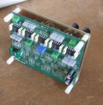
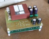
pinkmouse said:PSU is my own design, made up simply so I could use up some transfomers I had lying around. The vacant space is for an on/off mute delay circuit. I'll add that in once I know what sort of delays I need for silent operation.
Looks like you were a bit tight with the dimensioning of the Tx and the white PCB terminals...
😀
OK guys, you caught me out! Let the connector issue be a lesson to always check your Eagle footprints against what you have to hand, and as for the drill bit, my only excuse is that I've been making a lot of PCBs recently... 🙂
dual vs single opamps?
I have been looking for very high quality opamps to match my system. The best sounding opamps that I have found are the OPA627bp and OPA637bp single opamps.
In fact these opamps may be higher quality than my original Musical Fidelity Trivista DAC. If that is the case, these should be good enough since they would be better sounding than my source.
Could I get these to work with the active crossover if I stuck to a simpler 6 db per octave design?
If this will not work, what would be equivalent to those chips, but in a dual form?
The reviews on these chips mentioned they are laid back with a lot of depth and a lot of resolution. The OPA637bp is supposed to be livier than the OPA627bp. They did mention the cheaper opa2134 opamps too, but said they did not have as much spaciousness as these single opa627/637 opamps.
I do not know what livier means brighter? That would be less neutral? I have seen one review site mention they felt the 637 was better than the 627, although the 637 was toucher if you went below a gain of 4. In that case, the 627 was more stable.
Thanks for any additional advice in advance.
I thought these chips were ridiculously expensive at $27.00 or so a piece. So, that was another reason why I thought 6 db per octive to keep costs down, but being able to buy something better than my trivista dac source.
So, I am always open for cheaper alternatives that could be equivalent. I have not tried any of them, so do not have any comparisons of each.
Bill
It may be going against received wisdom, but in my opionion, in low gain applications, the 2134s sound virtually as good as the 627s, and the slight improvement certainly isn't worth twenty times the cost. The board would also need lots of tweaking to work with single opamps, (though not as much as trying to shoehorn INA134s onto it, as I am! 🙂 )
LM6172IN
Well, I decided to try the LM6172in.
I have read a lot of positive comments on this device, so I ordered some samples from National to try out.
They charged for the shipping, but I will be receiving 4 of them.
Is that enough to try my 6 db crossover? I should just order samples of what people say sound good and try them in a simple two way crossover to see the sonics and how well they sound and match my system.
I will have to install sockets to try my various flavors. 🙂
Bill
Four dual opamps would work for a single channel at 6 or 12 db/octave. You could get away with 3 if you skip the output buffer and just use the buffer provided by the filter section.
- Status
- Not open for further replies.
- Home
- Group Buys
- Active filter board GB