AP Linkage
I want to put the AP filter in the HP section & I assume I should do this by installing a link (see attached) between JP8Pin 1 to the AP IN & then from the AP OUT to the JP8 pin 2, is that correct?
In the AP filter & the EQ filters there are ground points on the inputs & outputs but I dont understand why. How should they be used. Is the idea to run a ground wire from say near JP8 for the AP so that the AP ground is closely linked to the HP circuit section?
Attachments
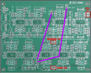
That looks correct. Ideally you'll take your signal and return out together. Since the board's ground plane connects all grounds you can probably get away with just running a signal wire. It wouldn't hurt to carry the ground back from both all pass connections twisted with the signal lead. If you get any hum do this and terminate the grounds at the HP out ground pin.
Header connections with ground were included in case you were cascading all pass sections on two different boards.
Header connections with ground were included in case you were cascading all pass sections on two different boards.
That looks correct. Ideally you'll take your signal and return out together. Since the board's ground plane connects all grounds you can probably get away with just running a signal wire. It wouldn't hurt to carry the ground back from both all pass connections twisted with the signal lead. If you get any hum do this and terminate the grounds at the HP out ground pin.
Header connections with ground were included in case you were cascading all pass sections on two different boards.
Thank you
Bob
The PSU (15V) boards have trimmer resistor locations marked as P1 & P2 but they are not in the BOM? are they required?
Also in the BOM (that I have) 2 resistances are give for R11 & 13, from what I can surmise I should use the 2K for the 15V & not the 3.3K, is that correct.
The PSU (15V) boards have trimmer resistor locations marked as P1 & P2 but they are not in the BOM? are they required?
Also in the BOM (that I have) 2 resistances are give for R11 & 13, from what I can surmise I should use the 2K for the 15V & not the 3.3K, is that correct.
The trimpots are there for those who want to get exactly the same rails or have some adjustability. Use 10k and 3K3 and you'll be able to adjust a bit either side of 15V. Use 2K and you'll be within a few mV of 15V.
In case you didn't guess, trimpots weren't included in the kits as a cost saving measure.
In case you didn't guess, trimpots weren't included in the kits as a cost saving measure.
Last edited:
I still have 2 positive and 2 negative PSU boards, build and tested, that are gathering dust. Anyone interested?
PSU Issue
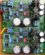
I have finally got to testing the PSU before connecting it to the Crossover and have run into a problem. On the + side I am getting 15V on the out but on the - side I am only getting -3.96v on the out I have attached a couple of photo's in the hope you might be able to give me an idea of where I have gone wrong or what/how I should test to work out where the problem is. Both sides are getting 18v ac on the input.
The boards and parts where sitting around in Greece for many years & where a little bit worse for wear (oxidization etc) when I got them, I tried to clean them up but was a little concerned I may have issues. Of course this problem many have nothing to do with that.
Attachments
Sounds like you have a failure to start on the negative side. Try increasing R19. Jens had good results with 1.2-1.5K. I just omit R19 and R4 all together and haven't been able to hear a difference.
In theory cleaner power to the reference will make the regulator perform better, but I think the LM4040 is stable and quiet enough with a 1uF cap across it that it doesn't matter. If you want to clean up the power without using the R4/19 references to the output, you can substitute a current regulating diode for R3 and R18 and omit R4 and R19. You don't need much current with an LM4040, a couple mA is plenty. For example you can use http://www.mouser.com/ProductDetail...GAEpiMZZMtQ8nqTKtFS/IesVZ6Shf/oZbD%2bWWtpFG4=
Hope this helps and keep us posted on your results.
Last edited:
Well I couldn't wait 🙂 (bugger the mowing) so I cut out R19 on the negative side only, as it is the problem side & I now have -1.99V on the out. Both R4 & R19 were 950ohms. with R4 still in place the + side is giving 15.15v out.
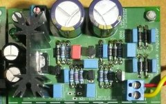
On closer examination, do you have something in D9 AND D10? It looks like you have a 1n400x in D10. When using D9, you don't populate D10. Since you seem to have an LM4040 in D9, remove whatever you have loaded in D10 and try again. Be sure that D9 is an LM4040 not a BC5xx. I know I need a magnifying glass and a bright light to read part numbers.
Is D15 oriented correctly?
If that doesn't solve the problem, measure the voltages at each pin of T5 and T6 referenced to ground.
Is D15 oriented correctly?
If that doesn't solve the problem, measure the voltages at each pin of T5 and T6 referenced to ground.
Last edited:
On closer examination, do you have something in D9 AND D10? It looks like you have a 1n400x in D10. When using D9, you don't populate D10. Since you seem to have an LM4040 in D9, remove whatever you have loaded in D10 and try again. Be sure that D9 is an LM4040 not a BC5xx. I know I need a magnifying glass and a bright light to read part numbers.
Is D15 oriented correctly?
If that doesn't solve the problem, measure the voltages at each pin of T5 and T6 referenced to ground.
There was an issue with T6 it had some wacky voltages, R20 & R21 seemed to be bridge & were both reading 500 ohms rather then 1k. I did a cleanup on T6 and the resistors and everything is good now. I put R19 back in and removed D10 and it's cousin on the + side, not sure what happened there, I assume if D9 isn't used a Zener goes D10?
Yes D15 was ok
Now to try the crossover, hopefully it will be a smoke free zone 🙂
One more question, if only 1 half of a OPA is being used should anything be done with the other half. I vaguely remember (crappy memory) having issues with the Linkwitz ASP and the OPA's overheating, I had to do something?? to the unused half of the OPA to stop the issues.
Many thanks Bob
Last edited:
Sounds like all I did was advise you to troubleshoot your board. Glad you've got it up and running.
D9 and D10 were there to provide options for the voltage reference, either an LM4040 or a zener. The latter is usually noisier and a bit less accurate. Some applications might choose a zener for its availability in higher voltage specifications. For example, substituting a 20V zener you have a 30V supply with no other value changes (but watch dissipation in the voltage divider at the output , R2,13, etc.
D9 and D10 were there to provide options for the voltage reference, either an LM4040 or a zener. The latter is usually noisier and a bit less accurate. Some applications might choose a zener for its availability in higher voltage specifications. For example, substituting a 20V zener you have a 30V supply with no other value changes (but watch dissipation in the voltage divider at the output , R2,13, etc.
Bob
Any thoughts on the;
"One more question, if only 1 half of a OPA is being used should anything be done with the other half. I vaguely remember having issues with the Linkwitz ASP and the OPA's overheating, I had to do something?? to the unused half of the OPA to stop the issues."
Any thoughts on the;
"One more question, if only 1 half of a OPA is being used should anything be done with the other half. I vaguely remember having issues with the Linkwitz ASP and the OPA's overheating, I had to do something?? to the unused half of the OPA to stop the issues."
If you had issues with the op-amps overheating in the Linkwitz ASP's, then it probably wasn't related to unused sections. 🙂 The ASP board ties inputs of unused sections to ground (via a resistor) so the op-amp stays in the middle of the +/- voltage applied.
It's a good common practice to tie the output back to the inverting input and put a resistor to ground from the non-inverting input for all unused op-amp devices.
Cheers,
Dave.
It's a good common practice to tie the output back to the inverting input and put a resistor to ground from the non-inverting input for all unused op-amp devices.
Cheers,
Dave.
It's a good common practice to tie the output back to the inverting input and put a resistor to ground from the non-inverting input for all unused op-amp devices.
Cheers,
Dave.
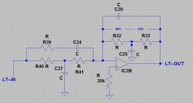
Like attached?
The resistors and capacitors wont be installed, I'll install a link between R33 & R32, and install a 20K?? resister to ground off the + Input. As the +Input appears to be linked directly to ground at the moment I'll have to lift the leg to install the resister
Attachments
No, that's a different setup because the op-amp configuration is inverting.
In this case you're actually using the op-amp but just need to configure it for unity gain and no EQ. You'd want to load a resistor combination into the R32/R33 locations and also another into the series location left of your schematic. You'd also want to load an appropriate small value capacitor into C20 to reduce gain at frequencies above the audio band.
Cheers,
Dave.
No, that's a different setup because the op-amp configuration is inverting.
In this case you're actually using the op-amp but just need to configure it for unity gain and no EQ. You'd want to load a resistor combination into the R32/R33 locations and also another into the series location left of your schematic. You'd also want to load an appropriate small value capacitor into C20 to reduce gain at frequencies above the audio band.
Cheers,
Dave.
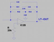
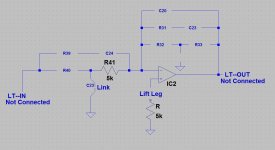
Hmm, when you say "In this case you're actually using the op-amp" I'm not sure exactly what you mean. The other half of the OPA 2134 is used for an All PASS section but the only things on this half (LT half) that is actually connected to the circuit is the + IN, as it is directly connected to ground , the -IN and the OUT are floating and to bring them into the circuit I need to install links to the LT-IN & LT-OUT (Linkwitz Transform) I have attached a drawing of the whole section of the circuit.
Perhaps I could lift the +IN leg, link it to the OUT, then tie the -IN to Ground via a resistor (any thoughts on resistor value?) as shown in the other attachment.
Attachments

Last edited:
No, you've created and oscillator. Just jumper or use 1-10K from both inputs to ground if you aren't using that half of the op amp. You could also jumper C20 and connect the +input to ground as above.
Your original "like this?" is an appropriate way to handle an unused op amp as well.
Your original "like this?" is an appropriate way to handle an unused op amp as well.
Last edited:
No, you've created and oscillator. Just jumper or use 1-10K from both inputs to ground if you aren't using that half of the op amp. You could also jumper C20 and connect the +input to ground as above.
Your original "like this?" is an appropriate way to handle an unused op amp as well.
OK +IN & -IN connected to ground via 5k resistors & nothing else connected.
Attachments
- Status
- Not open for further replies.
- Home
- Group Buys
- Active filter board GB