I've had a few requests for boards, but not enough to justify another buy. With nearly 2,000 AF4 boards out there, I suspect that there are a lot gathering dust.
If you are not going to use your boards, post their availability here and likely someone will snatch them up.
If you are not going to use your boards, post their availability here and likely someone will snatch them up.
Bob; I need to access the instructions for the Power Supply assembly. Could not get to them on your sight.
Thanks,
Pete
Thanks,
Pete
The schematic is here http://www.delta-audio.com/PSU two.htm
The 15 V and 65V BOMs are attached. Also in the zipfile is a spreadsheet for designing alternate voltages.
It's pretty much plug and play. Use only D7 and D9 or D8 and D10 - not both. The preference is LM4040 for lower noise, better stability.
Hey! This thing doesn't work!
I’ve built several of these power supplies and the only difficulties I had were caused by solder bridges on the prototype boards. The prototype boards did not have a soldermask, which made bridges an easy mistake to make. It’s still the first thing I’d look to if the board doesn’t function properly.
The next thing to check is component placement and orientation. The positive regulator uses two BC546 and a BC556 near the heat sink. Did you get that right?
Now check voltages relative to ground. If you used an LM4040, you should have nothing installed in the D10 position. Measure the voltage at the cathode side pad (band end), it should be 10V. The inboard end of R10 should be at 9.4V. You should have 1.2V across R1.
Some users have reported difficulty starting. If the regulator is supplied with at least 15VAC under the load you expect, there should be no problems. A 15 VAC nominal transformer with 10% regulation should provide 16.5 VAC under no load. This will result in >22VDC input. If you have difficulty starting, either use a higher voltage transformer or a transformer with a higher power rating. Using Avel's Y236203 (2 x 15VAC / 50 VA) the regulator starts reliably at up to 1A loads.
Attachments
Thanks for the input Bob, I'm just now getting around to building the crossover ---! Old age I guess.
Regards,
Pete
Regards,
Pete
Hi Bob,
Neewbie question.
I need to add one power on state Led to the PSU board.
Where could I place it, at the output ?
What is the formula to calculate the requested R ?
You've got a 3K3R with the green led, what is it's value ?
Thanks 🙂
Neewbie question.
I need to add one power on state Led to the PSU board.
Where could I place it, at the output ?
What is the formula to calculate the requested R ?
You've got a 3K3R with the green led, what is it's value ?
Thanks 🙂
Korben,
You could just take one or both of the leds off the board with leads, or you could go +15V to -15V.
The formula is (Vapplied-Vled)/Iled. In this case (15-2)/4
Assume 2V across the LED (green for red use 1.2V or 5V for blue)
Check your LED datasheet for the current desired. Usually 5-20 mA will give you as much light as you want. I chose ~4mA to keep them dim. I find 20 mA makes them too bright. You've got plenty of flexibility.
The spreadsheet I posted a few posts back will do the calculation for you at various output voltages and tell you what power rating you need.
Thank you Bob for the explanation, very helpful.
I'll have a try with it using a blue 3mm Led.
Could you send me the PDF about Active Filter ?
I'll have a try with it using a blue 3mm Led.
Could you send me the PDF about Active Filter ?
Thank you Bob, I've got the files.
I've missed that R6 value is indicated in your calculator. 😎
I've missed that R6 value is indicated in your calculator. 😎
BobEllis said:I've had a few requests for boards, but not enough to justify another buy. With nearly 2,000 AF4 boards out there, I suspect that there are a lot gathering dust.
If you are not going to use your boards, post their availability here and likely someone will snatch them up.

Hey guys - there are about 8 sets for sale including OPA2134s :
http://www.diyaudio.com/forums/showthread.php?postid=1647475#post1647475
My Blue Led specs tells it runs with 3.2v.
I've been successful in using 1K8 as R6 value.
It shines pretty good just like I taste.
Thank you Bob
I've been successful in using 1K8 as R6 value.
It shines pretty good just like I taste.
Thank you Bob

eliminating buffers in EQ-section
Hi members,
I plan to build an active crossover for my Apogee.
I'll need three EQ Sections (all notch filter).
Is it possible to cascade the three eq's and use only one output buffer, like: input buffer --> eq1 --> eq2 --> eq3 --> output buffer.
(in the circuit given in the excel-spreadsheet, all eq's have an output buffer of their own)
Thank you for clarification.
Olaf
Olaf -
It is possible but the sections will interact with each other and the overall response will not be what my spreadsheet will predict.
If you want to do it that way, I suggest simulating the circuit rather than trying to calculate it manually.
It is possible but the sections will interact with each other and the overall response will not be what my spreadsheet will predict.
If you want to do it that way, I suggest simulating the circuit rather than trying to calculate it manually.
BobEllis said:Olaf -
It is possible but the sections will interact with each other and the overall response will not be what my spreadsheet will predict.
If you want to do it that way, I suggest simulating the circuit rather than trying to calculate it manually.
I agree on the first point - it is possible but you need to do some analysis of how much each section will disturbe the next. This will depend on Q + cut.
Calculation will be possible, as long as you use the input impedance of each EQ section to predict the overall response....
IMO this is best done with something like MathCAD, but I guess another cheaper solutions would be to download LTspice (or another free simulator) and simulate the whole thing.... this gives you the freedom to use non ideal opamps (something that is not easy with mathCAD).....
\\\Jens
Scaling in LTspice?
Hello (hope not too much OT),
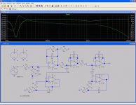
I managed to simulate my desired crossover in LTSpice (nice tool btw.)
My problem is the scaling in the y-axis (dB). How can I manage to scale it right (in the spreadsheet I choose -16 and -4 dB attenuation).
This attenuation is not reflected in the scale )see attached screenshot.
Thank you for tips
P.S. leaving the buffers away is a pain, I gave up to simulate this.
Hello (hope not too much OT),
I managed to simulate my desired crossover in LTSpice (nice tool btw.)
My problem is the scaling in the y-axis (dB). How can I manage to scale it right (in the spreadsheet I choose -16 and -4 dB attenuation).
This attenuation is not reflected in the scale )see attached screenshot.
Thank you for tips
P.S. leaving the buffers away is a pain, I gave up to simulate this.
Attachments
A power supply question.
My amplifier has +/-34V rails. Can I just use +/-15V regulator chips to get my crossover supplies?
My amplifier has +/-34V rails. Can I just use +/-15V regulator chips to get my crossover supplies?
The higher the voltage you are dropping, the more heat you will generate. If you want to try (regulator chips are cheap!), use big heat sinks. You could also just go to the data sheet for the regulator chips and see what the max input voltage is, but that wouldn't be nearly as amusing. 🙂
David
David
- Status
- Not open for further replies.
- Home
- Group Buys
- Active filter board GB