Butterworth characteristic requires Q to be 1/SqRt(2)=0.707
A three pole Butterworth uses a cascaded pair of passive single pole and active two pole.
The passive has a Q=0.707, this requires the active two pole to have Q=1.0
A three pole Butterworth uses a cascaded pair of passive single pole and active two pole.
The passive has a Q=0.707, this requires the active two pole to have Q=1.0
Phillipe -
Q refers to the shape of the filter - lower Q filters have a shallow initial rolloff before reaching their final rolloff. Higher Q filters have sharper corners and may even have a peak before rolling off.
I've forgotten the Q of a butterworth filter, but there is more to it than the electrical filter slope. You need to combine the response of the driver with with the filter to get the net acoustic response you desire.
You may find that you can use a 2nd order electrical filter to achieve a 3rd or even fourth order target depending on the drivers.
Before inexpensive simulators, we used the named filter shapes because there were tables to help us calculate component values. Now just plug your measured data into a sim program and adjust the filter to reach your target response.
It's a little more work with free programs, but you can use an electrical simulator like LTSpice to generate a filter with the transfer function created in something like speaker workshop. Simulate, build, measure, adjust the sim to match measured data, repeat.
News for those on the Waiting List
Hi Bob,
I was just wondering (since there seems to be little activity on the Forum) whether there was any (good) news for those of us on the waiting list?
Thanks
Alan
Hi Bob,
I was just wondering (since there seems to be little activity on the Forum) whether there was any (good) news for those of us on the waiting list?
Thanks
Alan
Yes, Alan, I'm just about ready to release the leftovers. You should be hearing from me shortly.
boards
I might have 6 unused boards and a whole lot of opamps, R's and Cs. Hang on and I'll let you know soon.
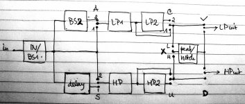
I might also have a hard wired 2way bread board with
- input amp with possibility of baffle step (as this approached the desired transfer function better than a 1st order baffle step)
- possibility of 2nd order baffle step
- 2 2nd order LP filters (order 1-4 to be selected with hard wire and jumpers)
- 2 2nd order HP filters (as LP)
- 2 delay functions (1-2 to be selected with hard wire)
- a peak/notch filter (can be inserted in LP or in HP filter)
Everything with multiple R's (easily changable and selectionable with jumpers).
See attachment of block schematic of the board.
Anyone interested? (I can send photos and a more detailed description).
I might have 6 unused boards and a whole lot of opamps, R's and Cs. Hang on and I'll let you know soon.
I might also have a hard wired 2way bread board with
- input amp with possibility of baffle step (as this approached the desired transfer function better than a 1st order baffle step)
- possibility of 2nd order baffle step
- 2 2nd order LP filters (order 1-4 to be selected with hard wire and jumpers)
- 2 2nd order HP filters (as LP)
- 2 delay functions (1-2 to be selected with hard wire)
- a peak/notch filter (can be inserted in LP or in HP filter)
Everything with multiple R's (easily changable and selectionable with jumpers).
See attachment of block schematic of the board.
Anyone interested? (I can send photos and a more detailed description).
Attachments
I have to withdraw part of my offer. I can spare
- 2 unused boards
- 12 opamps OPA 2134
What's the price of boards and Opa's these days?
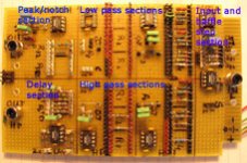
The offer of the bread bord will have to be postponed for (probably) months. Nonetheless I include a picture of it (sorry for the small size but the forum doesn't allow a better picture. Mail me and I'll send a better one).
Dick.
- 2 unused boards
- 12 opamps OPA 2134
What's the price of boards and Opa's these days?
The offer of the bread bord will have to be postponed for (probably) months. Nonetheless I include a picture of it (sorry for the small size but the forum doesn't allow a better picture. Mail me and I'll send a better one).
Dick.
Attachments
filter for subwoofer
Hi all
Subwoofers often have the option of changing phase.
Does anyone know how this is done? Is it in fact a timeshift function?
Thanks
Dick.
Hi all
Subwoofers often have the option of changing phase.
Does anyone know how this is done? Is it in fact a timeshift function?
Thanks
Dick.
probably done with an opamp and switch to convert between inverting and non-inverting mode.
Some have an adjustable phase control. How?
Some have an adjustable phase control. How?
Hi,
Maybe something like this: http://www.lcaudio.com/pdfs/subfilter.pdf
Although I'm unsure how accurate (not much) the phase adjust is.....
\\\Jens
Maybe something like this: http://www.lcaudio.com/pdfs/subfilter.pdf
Although I'm unsure how accurate (not much) the phase adjust is.....
\\\Jens
thanks bob and andrew.
can you have a look on this configuration in order to verify if j have well understood your advices
Thanks philippe
buttenworth 3 order filter
first stage is passive with just C and r (no OPA)
second stage is active with Q=1
can you have a look on this configuration in order to verify if j have well understood your advices
Thanks philippe
buttenworth 3 order filter
first stage is passive with just C and r (no OPA)
second stage is active with Q=1
Attachments
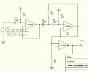
I think this will only be a second order filter.
Make the first stage active (skip the wire from input to output of IC4B and shor R14) and add a C between output IC4B and R16.
Make the first stage active (skip the wire from input to output of IC4B and shor R14) and add a C between output IC4B and R16.
Sorry, my mistake. I didn't see the second page of your attachment.
With that taken into account you'll get a 4th order filter.
I see though that IC4 a and b occur twice (even three times!). If you delete the first one altogether you'll have a 3rd order filter.
Delete R6 and feed your input directly into C4.
IC4B (the first one) can be bypassed by feeding the following section directly from the output of IC4A.
Like this:
Attachments
Attention wait listers
You should have received an email with payment instructions. So far I have only received payment from 3 of you. I'll hold them through next weekend and then let them go to the first paying parties.
You should have received an email with payment instructions. So far I have only received payment from 3 of you. I'll hold them through next weekend and then let them go to the first paying parties.
Bobelis,
For some days, j can't access to your website in order to download the manual, is it possible to post it.
j am looking for the balanced configuration . R values.
Thanks
Philippe
For some days, j can't access to your website in order to download the manual, is it possible to post it.
j am looking for the balanced configuration . R values.
Thanks
Philippe
Phillipe -
I changed ISPs and haven't had a chance to build the new site. The AF 4 manual is too big to post here, I'll send you a copy if you like.
I've attached the spreadsheet, which really has all you need in it. For balanced input, just pick an input impedance and use that for R11, 12, 13 and 16. 10K works well for most sources. For DSC/dipole compensation it gets a bit trickier, if you are using a three way or more, I'd just use one of the otherwise unused buffer/shelving sections after the balanced to single ended conversion.
If you must use the balanced input and baffle step in one stage,
3.1.7 Baffle Step Compensation
The balanced input can also be configured to provide baffle step compensation, although not all components will be on the board. Figure R12 and R16 as in the single ended case and then set R11=R12 and R13=R16. Place a capacitor identical to C10 across R11.
To provide bandwidth limiting, place a 5nF capacitor across In+ and In- and connect one end of a 100R resistor to the In+ and In-pads. The other ends of your resistors are now the input connections.
Attachments
- Status
- Not open for further replies.
- Home
- Group Buys
- Active filter board GB