No, there wasn't enough room for that option. If there was I'd have gone for another all pass section anyway.
For a balanced line driver, see the Twisted Pear guys - they were working on some interesting stuff using a TI chip that is suspected of using the Pass "X" patent (legally).
You could also use something conventional like a DRV-134. It should be easy to build the circuit on a prototype board.
Another option would be to build an inverting buffer and feed it with the signal being input to the AF4 board's buffer (at the attenuator).
I haven't decided which way I want to go yet... (probably try them all and see)
I just received my boards.
The boards are an order of magnitude better than I expected!
Bob, you do excellent work.
The boards are an order of magnitude better than I expected!
Bob, you do excellent work.
Jens did the board designs, I just had them manufactured. He deserves the praise and thanks. Please offer a toast to Jens 
One thing to note with the PSU kits - there seems to be a worldwide shortage of MJE15032/33, with a lead time that would have pushed shipment back to December or later. I substituted MJE15034/35 in the kits. Use the 34 in place of the 32 and the 35 in place of the 33. The devices supplied have a little higher hfe, but the specifications are otherwise virtually identical.
One thing to note with the PSU kits - there seems to be a worldwide shortage of MJE15032/33, with a lead time that would have pushed shipment back to December or later. I substituted MJE15034/35 in the kits. Use the 34 in place of the 32 and the 35 in place of the 33. The devices supplied have a little higher hfe, but the specifications are otherwise virtually identical.
They should be fine, although their gain is not as high as the 32/33. It's almost like Onsemi decided to assign different part numbers to the same device with different gains rather than grade them according to gain.
The last of the orders will ship tomorrow, with the exception of those who have not provided me with some shipping details. Check the email address associated with your paypal account or the one you used to correspond with me. If you haven't received a shipment notice you should have received an explanation of why not.
Hi guys
And now for something completely different (I'm a big fan of Monty Python):
A while ago someone made a remark on timedelay. This will work nicely I suppose if the filter has a smooth phase response at crossover.
In my design I have to put a notch filter just under cross over (at the resonance frequency of the tweeter).
This messes up the phase response completely (and the working of the all pass section).
Has anyone experience on this point?
I know I'll have to try and listen but any advice beforehand would be welcome.
Dick.
PS: one all pass section will in most cases not be enough
Dick,
Can you post a picture of what your phase relationships look like before and after the all pass?
Have you tried reversing the placement of the notch and all pass in your signal chain? What is the rest of your filter topology? Assuming that you are still simulating it, does the simulated circuit accurately reflect what you will use on the board? (skipped buffers, etc.)
It would take a little surgery, but the Linkwitz transform section can be converted to an all pass section if needed.
After looking through my older software CD's i found Cooledit pro(now Adobe audition).
It is able to simulate Bessel,Butterworth,Chebychev,low cut,high cut,bandpass,band stop etc. up to 10th order in 32 bit quality if you wish.
It has FFT filters and parametric equalisers.All in proper dB scales . You can use constant Q filters and view phase and delay etc.
you can apply the filters per channel and add filters after each other (bass boost and high cut etc).
The only drawback is that you can't use it in real time.I record a sample or CD track and apply the filters i want to try out.Then store and playback the channels through the different speakers.
It gives you a way to listen before you build.
Next week i'll try a friends Adobe audition to see if it has more functions except a CPU unfriendly interface.
I don't want to advertise anybody's software and perhaps there are other/better programms out there but i find it usefull in trying out different setups.
kro5998
Hi,
first a BIG thank you to Jens and Bob!
My kit has arrived!!
Ok I need to get the transformer,
from RS (rswww.com)
Part numbers
223-7901 50VA 2x 15v output
223-7917 50VA 2X 18v output
I have been reading the threads, both 15v and 18v mentioned, both transformers cost the same from RS
Which should I get tomorrow morning?
I assembled the power supply and everything is A-OK. Thanks Jens and Bob.
I don't have a tranny to use yet. I fed DC into the bridge and it handled the polarity auto-magically.
...I had a couple of 15-turn 10k pots lying around for the adjustment. I glued them on end so they stand up vertically.
I don't have a tranny to use yet. I fed DC into the bridge and it handled the polarity auto-magically.
...I had a couple of 15-turn 10k pots lying around for the adjustment. I glued them on end so they stand up vertically.
Toroid ac voltage rating?
Can I get away with 20 or 21 volts for the AC voltage of the secondaries?
I have some 80 Va toroids lying around if that would be okay? Would the voltage regulator handle that high. I believe I measured 20.5 volts AC previously.
Thanks, Bill
Can I get away with 20 or 21 volts for the AC voltage of the secondaries?
I have some 80 Va toroids lying around if that would be okay? Would the voltage regulator handle that high. I believe I measured 20.5 volts AC previously.
Thanks, Bill
for transformers, 15 volts/25+VA should be plenty.
If you want to go higher, watch the dissipation in the pass devices. It should be limited to 5W or so with the 2" sinks supplied with the kit. the spreadsheet on my web page will show you the max current you can deliver - enter the DC input voltage and the rest is calculated for you.
If you want to go higher, watch the dissipation in the pass devices. It should be limited to 5W or so with the 2" sinks supplied with the kit. the spreadsheet on my web page will show you the max current you can deliver - enter the DC input voltage and the rest is calculated for you.
BobEllis said:
Can you post a picture of what your phase relationships look like before and after the all pass?
Have you tried reversing the placement of the notch and all pass in your signal chain? What is the rest of your filter topology? Assuming that you are still simulating it, does the simulated circuit accurately reflect what you will use on the board? (skipped buffers, etc.)
Hoi Bob,
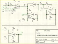
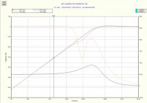
Here is the picture of the schematic : first element 2nd order HP, 2nd element notch filter, 3rd and 4th element all pass filters ).
Have a look at the delay reponse in next posting: it shows a severe dip at 2 kHz as a result of the notch filter.
I intend to accurately build the filter as designed (no buffers therefore).
Dick.
Attachments
- Status
- Not open for further replies.
- Home
- Group Buys
- Active filter board GB