It seems that there have been several different active crossover boards for DIY loudspeakers put forth on this forum. Well, I'd like to make yet another permutation of this highly useful and needed piece of hardware.
The capabilities that I would like to include on the "basic board" are:
The filter and equalizer functionality of the basic board will be expandable using an add on board that will have several second order circuit sections that can implement either an HP/LP filter or a BP. The HP and LP outputs can be used to increase the order of the crossover on the basic board, or to make a 4- or higher way second order crossover. The BP outputs can be routed back to create additional equalizer bands, useful if your drivers have breakup peaks that need to be notched out, or if there is a dip in the response that needs to be lifted to flatten the FR. The add-on board will probably have 4 second order sections.
I want the circuit to be general in the sense that it could be built up fully and then, by adjusting potentiometers, the parameters (e.g. Q, frequency, etc.) can be modified as needed. In this way the board would be re-usable, or adjustable at a later date to accommodate a change or to implement a tweak in the frequency response of the speaker. Each 2nd order section on the add-on board will have its own I/O connectors, so you can configure it in various ways as needed.
All of the filter functions will be implemented using 3-op-amp state-variable filters. The advantage of the SVFs is that all parameters are independently adjustable via potentiometers (trimmer types). I also plan to make it possible to convert all the potentiometers to fixed resistors.
I'd like to get some feedback on this concept, and how much interest there would be in such a board. Would you be interested in bare PCBs or fully assembled and ready to go?
-Charlie
The capabilities that I would like to include on the "basic board" are:
* Baffle Step with adjustable frequency and gain
* One equalizer band with adjustable center frequency and cut/boost level
* One second order symmetric LP/HP filters with adjustable Q and frequency
* One equalizer band with adjustable center frequency and cut/boost level
* One second order symmetric LP/HP filters with adjustable Q and frequency
The filter and equalizer functionality of the basic board will be expandable using an add on board that will have several second order circuit sections that can implement either an HP/LP filter or a BP. The HP and LP outputs can be used to increase the order of the crossover on the basic board, or to make a 4- or higher way second order crossover. The BP outputs can be routed back to create additional equalizer bands, useful if your drivers have breakup peaks that need to be notched out, or if there is a dip in the response that needs to be lifted to flatten the FR. The add-on board will probably have 4 second order sections.
I want the circuit to be general in the sense that it could be built up fully and then, by adjusting potentiometers, the parameters (e.g. Q, frequency, etc.) can be modified as needed. In this way the board would be re-usable, or adjustable at a later date to accommodate a change or to implement a tweak in the frequency response of the speaker. Each 2nd order section on the add-on board will have its own I/O connectors, so you can configure it in various ways as needed.
All of the filter functions will be implemented using 3-op-amp state-variable filters. The advantage of the SVFs is that all parameters are independently adjustable via potentiometers (trimmer types). I also plan to make it possible to convert all the potentiometers to fixed resistors.
I'd like to get some feedback on this concept, and how much interest there would be in such a board. Would you be interested in bare PCBs or fully assembled and ready to go?
-Charlie
Hi Charlie,
I understand your desire for a prototyping board that can also be used for a finished product. However, the board real estate required for the pots and resistors to replace them would mean that you'll end up with a fairly large board. It might make more sense to make a prototyping board and a finished board. I'd like to see a board with SMD parts - even though it would be a challenge to assemble at my age and I have a boatload of through hole OPA2134s.
You should have some bandwidth limiting on the input. You may have thought of this already but didn't mention it. Allow for a decent size cap - you'll see why below.
You might want to breadboard a state variable filter and a Sallen-Key filter to see if you can hear a difference and like the state variable sound. I've heard that state variables don't sound as good, although there are plenty of folks who love the state variable Marchand XOs.
Jens' AF-4 implementation of the Sallen-Key gives adjustable Q while holding the gain to 1 using two opamps per 12 db/octave section. You could use pots for frequency and Q setting.
Have you simulated to see what happens when your pots don't track? Might be an issue, might not. You may be able to get some frequency spread to adjust phase adjusting them individually, but then the math gets more interesting.
If you cannot get phase adjustment in the state variable filter, I strongly suggest that you provide and all pass section or two (another argument for SMD) You can use a pot for the prototype stage to set the shift. If you set up the baffle step input buffer with jumpers to allow the right connections you can use it as an all pass in a three way set up.
An option to make your settings adjustable would be to use sockets on the board to allow replacement of resistors or connection of pots, like you would probably use for your add on board. They can usually be snapped apart to allow single terminals to be placed on 10mm pitch.
Are you planning a single channel or stereo board? If single channel, 4 second order filters on the add on board seems overkill. How about 2 second orders, an EQ and an all pass? I know it sounds like I am an all pass junkie, but take a look at the filter Linkwitz shows in his how to section. You need a bunch of them.
Let's see what you come up with and I'm sure lots of others will chime in with their wish lists, too.
Last edited:
I would advise against pots and instead use socceted resistors to reduce cost and increase perfomance. Also when one has finnished prototyping they could be soldered.
I would advise against pots and instead use socceted resistors to reduce cost and increase perfomance. Also when one has finnished prototyping they could be soldered.
I have some Marchand boards that use this approach and I don't like it. When I want to tweak the frequency, I have to come up with an entirely new set of 4 resistors, close in value, and then solder those on to a new header.
Hi Bob,
See my replies below.
It's not really a prototype board. It's a finished board with all components on it. The ICs will be socketed so people who are in to that kind roll ICs until they are happy. Resistors that will be unchanged could be SMDs, but few people want to tackle soldering SMD devices so that might hinder bare PCB sales. I'm envisioning the pots to be vertical trimmer types. These don't take up much room, and the pin spacing should allow them to be removed and a resistor put in their place (in case someone wants that). I'm just trying to allow for flexibility, it's not a requirement to replace the pots.
Sure, both LP and HP filtering of the input would be good. I can probably work this in, but it just adds more components.
I won't be using any dual pots. It's all done with trimmer pots, single gang, linear type. Tracking error is eliminated, but you have to separately adjust two pots to be the same resistance. I don't like dual pots of any kind, because of the tracking error issues.
I thought about delay using all-pass first and second order sections. This is getting a little fancy, and I think that 95% of users would not really use this or know how to, but this could be built on another add-on board that people could purchase separately. You just can not do all of this on one PCB. It will be too large and too expensive. If the initial board is well received, I would move on to make other things such as the delay board.
As I mentioned, everything is adjusted via pots and these can be exchanged for resistors, but you then need to solder and unsolder them to change anything. You could just stick with the pots for future adjustability.
This is currently planned as mono boards. The idea is to use these in active speakers, so there would need to be one channel in each speaker. If you want a stereo pair, you will need to get two.
I don't think that four second order sections is overkill and it should work out well in terms of PCB size and IC requirements. For instance, if you want to increase a 2-way crossover to 4th order you need to cascade one 2nd order section with the HP, and one with the LP. That would leave two left over, for another 2nd order HP/LP and perhaps another BP filter for the equalizer section. If you want to make a 3-way, you need even more sections. Note that you can split up the 2nd order sections any way you want between filter sections and equalizer sections.
See my replies below.
Hi Charlie,
I understand your desire for a prototyping board that can also be used for a finished product. However, the board real estate required for the pots and resistors to replace them would mean that you'll end up with a fairly large board. It might make more sense to make a prototyping board and a finished board. I'd like to see a board with SMD parts - even though it would be a challenge to assemble at my age and I have a boatload of through hole OPA2134s.
It's not really a prototype board. It's a finished board with all components on it. The ICs will be socketed so people who are in to that kind roll ICs until they are happy. Resistors that will be unchanged could be SMDs, but few people want to tackle soldering SMD devices so that might hinder bare PCB sales. I'm envisioning the pots to be vertical trimmer types. These don't take up much room, and the pin spacing should allow them to be removed and a resistor put in their place (in case someone wants that). I'm just trying to allow for flexibility, it's not a requirement to replace the pots.
You should have some bandwidth limiting on the input. You may have thought of this already but didn't mention it. Allow for a decent size cap - you'll see why below.
Sure, both LP and HP filtering of the input would be good. I can probably work this in, but it just adds more components.
You might want to breadboard a state variable filter and a Sallen-Key filter to see if you can hear a difference and like the state variable sound. I've heard that state variables don't sound as good, although there are plenty of folks who love the state variable Marchand XOs.
Jens' AF-4 implementation of the Sallen-Key gives adjustable Q while holding the gain to 1 using two opamps per 12 db/octave section. You could use pots for frequency and Q setting.
Have you simulated to see what happens when your pots don't track? Might be an issue, might not. You may be able to get some frequency spread to adjust phase adjusting them individually, but then the math gets more interesting.
I won't be using any dual pots. It's all done with trimmer pots, single gang, linear type. Tracking error is eliminated, but you have to separately adjust two pots to be the same resistance. I don't like dual pots of any kind, because of the tracking error issues.
If you cannot get phase adjustment in the state variable filter, I strongly suggest that you provide and all pass section or two (another argument for SMD) You can use a pot for the prototype stage to set the shift. If you set up the baffle step input buffer with jumpers to allow the right connections you can use it as an all pass in a three way set up.
I thought about delay using all-pass first and second order sections. This is getting a little fancy, and I think that 95% of users would not really use this or know how to, but this could be built on another add-on board that people could purchase separately. You just can not do all of this on one PCB. It will be too large and too expensive. If the initial board is well received, I would move on to make other things such as the delay board.
An option to make your settings adjustable would be to use sockets on the board to allow replacement of resistors or connection of pots, like you would probably use for your add on board. They can usually be snapped apart to allow single terminals to be placed on 10mm pitch.
Are you planning a single channel or stereo board? If single channel, 4 second order filters on the add on board seems overkill. How about 2 second orders, an EQ and an all pass? I know it sounds like I am an all pass junkie, but take a look at the filter Linkwitz shows in his how to section. You need a bunch of them.
As I mentioned, everything is adjusted via pots and these can be exchanged for resistors, but you then need to solder and unsolder them to change anything. You could just stick with the pots for future adjustability.
This is currently planned as mono boards. The idea is to use these in active speakers, so there would need to be one channel in each speaker. If you want a stereo pair, you will need to get two.
I don't think that four second order sections is overkill and it should work out well in terms of PCB size and IC requirements. For instance, if you want to increase a 2-way crossover to 4th order you need to cascade one 2nd order section with the HP, and one with the LP. That would leave two left over, for another 2nd order HP/LP and perhaps another BP filter for the equalizer section. If you want to make a 3-way, you need even more sections. Note that you can split up the 2nd order sections any way you want between filter sections and equalizer sections.
Let's see what you come up with and I'm sure lots of others will chime in with their wish lists, too.
Jens' AF-4 implementation of the Sallen-Key gives adjustable Q while holding the gain to 1 using two opamps per 12 db/octave section. You could use pots for frequency and Q setting.
That project is from 2005 or so. It seems that most of the info is now dead links. That was one of the reasons that I wanted to put this forward.
He may use 2 op-amps per SK filter, but with 3 per SVF I can get independent adjustability of all parameters, and better range of Q, increased circuit stability, etc. Also, with SK, you can only execute one function (e.g. HP or LP) at a time, so you can get mismatch between the two depending on component errors. The SVF executes LP and HP simultaneously, so these will always be matched, and the only error will be in the frequency or Q of BOTH.
-Charlie
Last edited:
That project is from 2005 or so. It seems that most of the info is now dead links. That was one of the reasons that I wanted to put this forward.
He may use 2 op-amps per SK filter, but with 3 per SVF I can get independent adjustability of all parameters, and better range of Q, increased circuit stability, etc. Also, with SK, you can only execute one function (e.g. HP or LP) at a time, so you can get mismatch between the two depending on component errors. The SVF executes LP and HP simultaneously, so these will always be matched, and the only error will be in the frequency or Q of BOTH.
-Charlie
By prototype board I meant one for dialing in the crossover.
That's one of the advantages of SK (and MFB or any separate implementation of high and low pass filters) - you can intentionally mismatch frequencies, slopes and Q to deal with driver response irregularities and roll off as well as do some or all of the needed phase adjustment without an all pass filter. I guess it amounts to design philosophy.
As for the all pass, users can always jumper it out if not being used (or as in Jens' design not jumper it in). After trying the same crossover with and without phase correction, I won't be doing without again. Even a couple where I just ballparked the offset before measuring worked out better than without. I wholeheartedly agree with Linkwitz' statement the without phase correction an active crossover is marginally useful.
Input LP can be as simple as an RC. Linkwitz uses a 3 pole filter (RCRCRC) but that's probably overkill.
Another useful feature would be a level adjust on the high pass. You should buffer the output, whether opamp or discrete follower. If you use a dual opamp, you'll have a spare for an all pass. 😉
By prototype board I meant one for dialing in the crossover.
That's one of the advantages of SK (and MFB or any separate implementation of high and low pass filters) - you can intentionally mismatch frequencies, slopes and Q to deal with driver response irregularities and roll off as well as do some or all of the needed phase adjustment without an all pass filter. I guess it amounts to design philosophy.
OK, I see now. Yes, that is definitely a valid approach - sort of a hangover from passive crossover design IMHO. I prefer matched crossovers, and then flattening frequency response first by driver level adjustments, then by active baffle step compensation followed by one or more bands of equalization.
Mismatching frequencies also will mismatch the phase in the crossover region, and this can lead to response irregularities, although they may not be significant or audible.
As for the all pass, users can always jumper it out if not being used (or as in Jens' design not jumper it in). After trying the same crossover with and without phase correction, I won't be doing without again. Even a couple where I just ballparked the offset before measuring worked out better than without. I wholeheartedly agree with Linkwitz' statement the without phase correction an active crossover is marginally useful.
True. The only problem I find is that you need to know how much offset you are compensating for. A single first order all pass can only do so much in terms of delay and one or more second order stages would be better. Multiple delay stages could be implemented in an adjustable way, but I think that would be better left for another board.
I don't really agree with SL WRT offset compensation. Look how many speakers with passive crossovers are out there that have nothing like that. Offset compensation via tweeter delay is something that has the potential to get you another 5% of performance, but only if there is a problem to solve in the first place. Odd frequency response irregularities in the crossover region (if they happen to be there at all) on account of the offset, can be remedied, but I am not sure that this is as much of a problem as SL suggests.
Input LP can be as simple as an RC. Linkwitz uses a 3 pole filter (RCRCRC) but that's probably overkill.
Another useful feature would be a level adjust on the high pass. You should buffer the output, whether opamp or discrete follower. If you use a dual opamp, you'll have a spare for an all pass. 😉
Yes, the input LP is definitely a good idea. Also a HP to reject radio frequency interference is equally good. First order for these is probably fine.
I'd plan to have an overall level (volume) control as part of the crossover. On the other hand, I prefer that the adjustment of the level of each driver be done at the amp, and this is pretty easy to do using a voltage divider pot or the like.
-Charlie
Just because you don't see a separate passive all pass section doesn't mean the designer hasn't adjusted the phase to a minimum error. When you see a nice deep reverse null it means the phases are pretty darned close. That rarely happens with a symmetrical filter.
You made my case for multiple all pass sections. 🙂 The first time I added phase correction my son noticed without being asked. It was a fairly dramatic change. I'm a believer. YMMV.
You made my case for multiple all pass sections. 🙂 The first time I added phase correction my son noticed without being asked. It was a fairly dramatic change. I'm a believer. YMMV.
Last edited:
Now at prototype stage...
I've manged to fit the circuit on a 3 x 3.5 inch PCB. Below is a screenshot of a 3-D rendering of the board, showing some component outlines.
Each board is a single channel and has:
Hopefully this board will be ready early next year. This will be offered as a kit, including PCB and parts. U-build it. The caps used are 1% Vishay and 5% Wima types, and resistors are 1% MF type.
-Charlie

I've manged to fit the circuit on a 3 x 3.5 inch PCB. Below is a screenshot of a 3-D rendering of the board, showing some component outlines.
Each board is a single channel and has:
* An expandable 2-way 2nd order crossover having adjustable frequency and Q
* A baffle step compensation circuit with adjustable step dB and center frequency
* An expandable fully parametric EQ with one on-board band
Once this board is in production, I plan to design and produce an expansion board that will allow the user to add additional 2nd order filter blocks and/or EQ bands. * A baffle step compensation circuit with adjustable step dB and center frequency
* An expandable fully parametric EQ with one on-board band
Hopefully this board will be ready early next year. This will be offered as a kit, including PCB and parts. U-build it. The caps used are 1% Vishay and 5% Wima types, and resistors are 1% MF type.
-Charlie
Hi,
just one remarks...Why don´t You design a fully flexible concept?
With this I mean a motherboard with multiple connectors for riser-cards.
At the moment the design is just a bit more flexible than all the other stuff described here. If You want different filters, different EQs, or discrete build (which btw sounds much better than all the OPamp stuff), it fails.
A motherboard as basis, holding the power supply, a sufficient amount of the connectors/riser-cards and -if needed- the µ-Controller or some logic, opens up far more opportunities.
If all the connectors/riser-cards are connected through a bus system, which would be simply a multiple of conducting traces on the PCB, the limit to flexibility is just limited by the number of connectors and the number of traces.
a simple implementation with 3 ports per channel can be seen here.
It uses an external power supply and single-sided PCB boads.
The settings may be done via Pots or jumpers which are esily accessible from the top.
crossover
jauu
Calvin
just one remarks...Why don´t You design a fully flexible concept?
With this I mean a motherboard with multiple connectors for riser-cards.
At the moment the design is just a bit more flexible than all the other stuff described here. If You want different filters, different EQs, or discrete build (which btw sounds much better than all the OPamp stuff), it fails.
A motherboard as basis, holding the power supply, a sufficient amount of the connectors/riser-cards and -if needed- the µ-Controller or some logic, opens up far more opportunities.
If all the connectors/riser-cards are connected through a bus system, which would be simply a multiple of conducting traces on the PCB, the limit to flexibility is just limited by the number of connectors and the number of traces.
a simple implementation with 3 ports per channel can be seen here.
It uses an external power supply and single-sided PCB boads.
The settings may be done via Pots or jumpers which are esily accessible from the top.
An externally hosted image should be here but it was not working when we last tested it.
crossover
jauu
Calvin
Last edited:
I did! All parameters are fully adjustable.Hi,
just one remarks...Why don´t You design a fully flexible concept?
With this I mean a motherboard with multiple connectors for riser-cards.
At the moment the design is just a bit more flexible than all the other stuff described here.
I think my design fits your idea of a "flexible concept". The adjustments are done via trim pots that can be accessed from the top. What you call the "motherboard" I call the "basic board". The add-on board will have the same footprint, and will provide additional fully adjustable second order sections that can be used either as HP/LP blocks or used as additional EQ blocks. Connections are made back to the "basic board" via wires.
One of the advantages of my modular design concept is that you can use the basic board to build a 2-way active monitor speaker, and then later build on a pair of subwoofers with a 2nd or 4th order crossover. To do this you can just get the add-on board to create the crossover from the monitor to the sub, as an expansion of the basic board. All board are small and can fit within the speaker(s). This is truly a flexible and expandable active crossover system.
-Charlie
Last edited:
Silly suggestions?
Maybe it's just me, but... how about different filter orders or center frequencies for the high-pass and low-pass stages of the crossover?
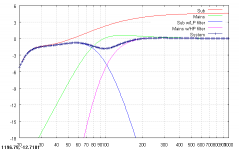
A system I built employs Jordan Jx92s speakers in .28 ft^3 sealed boxes with a subwoofer containing a 10" Peerless XLS driver and 10" passive radiator in a 1ft^3 box. The crossover needs to be in the 90 to 120Hz range. The F3 of the mains is around 70Hz. Theoretically, I get a flatter response when the sub's low pass is 24dB per octave and the main's high pass is 12dB per octave. Or I can get a nice flat theoretical response by using 24dB filters for both high-pass and low-pass, but using different center frequencies, say, 120Hz for the sub and 96Hz for the mains.
The first chart shows the theoretical response with a 24dB Linkwitz-Riley xover at 96Hz. In room, that setup has an actual suck-out at 100Hz of around 5dB, not 2dB as shown. I am compensating for it with a graphic equalizer.
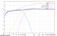
The second chart shows what happens, theoretically, when the high-pass filter is changed to 12dB/octave. Ahhh.
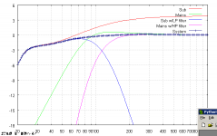
The third chart shows the effect of 24dB filters on both sub and main, but with the sub's filter centered at 120 and the main's at 96.
Maybe it's just me, but... how about different filter orders or center frequencies for the high-pass and low-pass stages of the crossover?
A system I built employs Jordan Jx92s speakers in .28 ft^3 sealed boxes with a subwoofer containing a 10" Peerless XLS driver and 10" passive radiator in a 1ft^3 box. The crossover needs to be in the 90 to 120Hz range. The F3 of the mains is around 70Hz. Theoretically, I get a flatter response when the sub's low pass is 24dB per octave and the main's high pass is 12dB per octave. Or I can get a nice flat theoretical response by using 24dB filters for both high-pass and low-pass, but using different center frequencies, say, 120Hz for the sub and 96Hz for the mains.
The first chart shows the theoretical response with a 24dB Linkwitz-Riley xover at 96Hz. In room, that setup has an actual suck-out at 100Hz of around 5dB, not 2dB as shown. I am compensating for it with a graphic equalizer.
The second chart shows what happens, theoretically, when the high-pass filter is changed to 12dB/octave. Ahhh.
The third chart shows the effect of 24dB filters on both sub and main, but with the sub's filter centered at 120 and the main's at 96.
Attachments
Last edited:
Maybe it's just me, but... how about different filter orders or center frequencies for the high-pass and low-pass stages of the crossover?
All parameters are adjustable - this includes the crossover frequencies.
To get higher order you must cascade the filter blocks - for instance, you will need three second order filter blocks to construct a single 4th order crossover. Only even order crossover filters can be constructed and the most useful one will be second order and/or fourth order as higher orders will require a ridiculous number of filter blocks to construct.
It sounds like what you really need is a flexible PA rackmount crossover. Behringer DCX2496 perhaps?
-Charlie
Sometimes one wants something other than an even order electrical filter. If you've got a driver that rolls off at 6db/octave at your chosen crossover frequency you only need a third order electrical filter to get a fourth order response. Maybe you could fit an optional RC or CR filter in the upper left corner of your board to allow odd order filters. Just a single jumper to bypass. Or move the power connection and electros up there and have the 1st order filters near the input.
Since we're going to want to set the frequency setting pots as we tweak maybe you could provide test points on the top of the board to measure the pots' values. Pads spaced for a jumper header would work.
Judging by the demand for pictures throughout the board, most of us are visual thinkers. Can you provide a schematic or block diagram of your filter board?
Last edited:
Sometimes one wants something other than an even order electrical filter. If you've got a driver that rolls off at 6db/octave at your chosen crossover frequency you only need a third order electrical filter to get a fourth order response. Maybe you could fit an optional RC or CR filter in the upper left corner of your board to allow odd order filters. Just a single jumper to bypass. Or move the power connection and electros up there and have the 1st order filters near the input.
Since we're going to want to set the frequency setting pots as we tweak maybe you could provide test points on the top of the board to measure the pots' values. Pads spaced for a jumper header would work.
Judging by the demand for pictures throughout the board, most of us are visual thinkers. Can you provide a schematic or block diagram of your filter board?
Hi Bob,
The boards have already been designed and sent out for prototyping. You are right, it would be nice to be able to implement odd order filters. I may throw in a couple of odd order sections on that extra board that will carry delay sections... but for now to keep things as simple as possible, I am sticking to second order sections and this means that only even order filters can be created. One could always put an RC network on the amp input if you know the input impedance. Since the intention is to build these crossover boards (and the amps) in to the speaker, the user should have that info available to them.
To make it possible to easily adjust the pots, I have a scheme to make them removable/pluggable using single pin sockets that can be installed in the mounting holes. I need to test this out, however, before I declare it viable. This is one thing that I will be trying out with the proto boards.
-Charlie
That works. I just wanted to be sure that there would be a way to get to the pots from the top of the board. You could leave a bit of lead exposed when the pots are in the sockets and have an easy way to measure. I'd guess that you wouldn't have too many insertions before leads cracked.
Good point about placing the 1st order filter between this board and the internal amp if needed. However, if I build a project with nice circuit boards it bugs me to air wire parts in or have a veroboard section I need to mount. Somehow though I always seem to do just that and/or perform surgery on boards to add something I forgot the first time around. 😉
Good point about placing the 1st order filter between this board and the internal amp if needed. However, if I build a project with nice circuit boards it bugs me to air wire parts in or have a veroboard section I need to mount. Somehow though I always seem to do just that and/or perform surgery on boards to add something I forgot the first time around. 😉
Last edited:
Overview, Block Diagram, and other useful info!
I have put together an overview of the crossover, with a flow diagram and some examples of how you can use the boards, in the linked PDF file (below). Please let me know if you have questions and I will try to answer them.
-Charlie
Click Here to view the Attachment: MODULAR CROSSOVER OVERVIEW.pdf
I have put together an overview of the crossover, with a flow diagram and some examples of how you can use the boards, in the linked PDF file (below). Please let me know if you have questions and I will try to answer them.
-Charlie
Click Here to view the Attachment: MODULAR CROSSOVER OVERVIEW.pdf
FYI - I made some minor corrections and additions to the crossover overview PDF document and uploaded the revised version.
-Charlie
-Charlie
some new options and things to consider...
I wanted to touch on a few items and get feedback from those people who are interested in the modular crossover boards. I have gotten some good input and questions over the past week, and I am considering making some changes that make possible some of these issues:
1. EQ - I came up with a combination input and EQ board for the first design iteration. This seemed to make sense and was a good use of the board space. But it was brought up that EQ for each driver might be desired. To address this, I wouldn't need to make any changes actually, but I would like to know if what I am proposing here sounds OK - It's possible to supply the input board without the input or power supply section and connect the input via a jumper wire directly to the EQ section. This reduces the part count significantly and because the EQ section uses its own dual op amp, it is more or less independent of the input and baffle step circuitry. So if people want a separate EQ for one (or more) drivers, they could buy the board in an "EQ only" version, and this would be relatively inexpensive. This means I would not need to develop and make yet another PCB for standalone EQ. If this approach sounds OK, then this issue seems to be resolved.
2. Balanced inputs - This was brought up to me in a thread on another forum. I actually agree that this is a good idea, since with active speakers the line-level cable runs will be longer. I am not sure that there really are any problems to be solved by balanced inputs, since I don't imagine people running 50'-100' of cable from their preamp to the speakers. If runs are kept under 20' and the right low capacitance unbalanced cables are used, I believe that things will be fine and there won't be undue noise pickup or high end roll off. But I don't live in an area with lots of RF interference, so I may not be sensitive to these kind of issues.
To allow for balanced inputs, I would probably want to develop a separate board that people could add on to the front end. It's extremely simple, since I would probably just use one of the off the shelf ICs like the INA134s that I mentioned in the last post. I would have room on the board for balanced outputs too, in case one wanted to send a signal externally (to a sub for instance). The board could probably be sold as 1 balanced input and 0,1,2, or 3 balanced outputs, depending on how many I can fit on the PCB. Whatever circuitry is unused would be left un-populated on the PCB.
3. Op-amps: I have to admit, by making everything "flexible" and "modular" I need to use a lot of op-amps in the designs. I was originally planning to use a moderately priced op-amp from OnSemi, the MC33274, which has pretty good but not top notch specs (MC datasheet). But for about $1.75 more per quad amp I can use an excellent quad op amp from National Semi, the LME49740 (LME datasheet). This will definitely raise the cost of each board a few dollars, but the distortion is several magnitudes lower (.003% for the OnSemi MC versus .00003% for the National LME) and noise is almost 10x lower (18 nV/ (sq. root Hz) for the OnSemi versus 2.7 nV/ (sq. root Hz) for the National). I was originally planning on socketing the op-amps, so that two different performance levels could be offered and op-amps could be swapped out, however it was suggested that the LME op-amps might not work well if socketed, because they are faster and have a much higher GBP. This makes board layout and bypassing much more important. It might work socketed or it might not. I just have to try it with the prototypes and see what happens. I would love to get some feedback on this from anyone who has designed and built PCBs using the newer fast op amps to learn about tips and tricks, etc.
For now, I would like to keep the idea of offering two performance levels of op-amps and socketing the devices and take a wait and see approach. How would people feel about not having two options but only having the more costly version available? Honestly, I believe that I need to keep costs down as much as possible without cutting any corners in order to keep these boards competitive with other crossover offerings out there...
So, those are my thoughts for now. I would love to get some feedback on these issues, and anything else that people might think of, so that I can work out everything in the near future.
Thanks,
-Charlie
- Status
- Not open for further replies.
- Home
- Source & Line
- Analog Line Level
- active crossover board capabilities - I want your input