JAM's alright....and more entertaining in person
Jam had dinner with both us because thought we could not possibly be as annoying in person as on line and to see if there really are two of us......... not once, but twice to determine if the first experience was some kind of aberration or a skillful attempt to bamboozle him. He said we were fine upstanding citizens and could rely on his endorsement anytime. He apologized repeatedly for drawing horns on my picture and said it would would NEVER happen again. I made him eat desert in a German restaurant to the accompaniment of a guy playing the accordion while wearing unwashed lederhosen (the accordion player, not Jam); as a test of his sincerity. As I have stated before, Texas abounds with examples of transplanted, but not diluted, fine European culture and sensibilities. We are truly proud to call it "The Vienna of the South" and challenge anyone find a more cosmopolitan experience anywhere in world.
Back to the topic of the week for the thread.....and since it's almost Christmas:
This week's message for owners of the Little Orphan Annie Transvox 5R5C decoder schematic.
J2 J9 C3 C4 2.3 KHz (12K 5700pF)
J2 J9 C4 C5 5.1 KHz (12K 3200pF)
J2 J9 C4 6.0KHz (12K 2200pF)
J2 J9 C5 13.0KHz (12K 1000pF)
Be be careful with that last one or "you'll short your high out!" and remember to drink your Ovaltine.
Auf Wiedersehen,
Fred Dieckmann
(whose late father actually owned lederhosen and played the accodianin his youth!)
PS
We got all three kinds, Country, Western, and German beer drinking music.
Attachments


Please don't provoke the Pass person here....
I think Mr. Pass's design is safe for a while longer as this not the basic discrete transistor topology referenced in the manual. The very ambitious can look at the DIY op amps article on the PassDIY website. Correct BJT transistor selection and compensation is a must. A recent attempt to piece together some parts from some Mr. Pass's designs as an "educated guess" as to this op amp design, resulted in an extremely unstable design that looked as if it had never been simulated much less built. You just can't throw together parts for a high bandwith feedback operation amplifier circuit, even if it only has a half a handful of parts. I really recommend building and measuring, and even listening to them before you post circuits, even after you have done a lot of Spice simulation. I have seen some stuff that might work in Spice but that would go nuts driving an actual interconnect of a few 10s to a few 100s of picofarads of capacitance.
I think Mr. Pass's design is safe for a while longer as this not the basic discrete transistor topology referenced in the manual. The very ambitious can look at the DIY op amps article on the PassDIY website. Correct BJT transistor selection and compensation is a must. A recent attempt to piece together some parts from some Mr. Pass's designs as an "educated guess" as to this op amp design, resulted in an extremely unstable design that looked as if it had never been simulated much less built. You just can't throw together parts for a high bandwith feedback operation amplifier circuit, even if it only has a half a handful of parts. I really recommend building and measuring, and even listening to them before you post circuits, even after you have done a lot of Spice simulation. I have seen some stuff that might work in Spice but that would go nuts driving an actual interconnect of a few 10s to a few 100s of picofarads of capacitance.
Attachments
As Grataku said
"Hey Fred, what's going on in this thread?
Is an discrete gain stage schematic coming or is this it?"
I could swear I posted such a circuit recently but can't remember just where exactly............ Getting old and foggy is a pain. Maybe someone else saw it or perhaps I imagined the whole thing. Maybe one of you young whippersnappers can figure it out.
"Hey Fred, what's going on in this thread?
Is an discrete gain stage schematic coming or is this it?"
I could swear I posted such a circuit recently but can't remember just where exactly............
Getting old and foggy is a pain. Maybe someone else saw it or perhaps I imagined the whole thing. Maybe one of you young whippersnappers can figure it out. Well Fred, I have tasted Texas hospitality and found it
second to none, and I have had dinner with Jam and he
is exceedingly good company. 😎
second to none, and I have had dinner with Jam and he
is exceedingly good company. 😎
Hey! what about me? where is _my_ dinner? I take my morning break at 2am while people are going out with Nelson and maybe getting freebies 😉
Never mix pleasure with pleasure.
Never mix pleasure with pleasure.
Cogito ergo Fred
"You'll short your eye out"
You really should consider a writing career. Too funny. Something to the effect of, Surely you must be Joking mister Dieckmann.
(I'm sure Feynman would aprove)
"You'll short your eye out"
You really should consider a writing career. Too funny. Something to the effect of, Surely you must be Joking mister Dieckmann.
(I'm sure Feynman would aprove)
Passing past Pass...
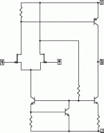
The opamp design I posted here meets two basic requirements: that the number of elements it contains is equal to that shown in the XVR1 manual and that the opamp functions properly based on that design. The picture below shows an experimental implementation of the design, which is a pretty good approximation of the topology that was most probably originally used by the Passlabs. It has been tested properly and works fine (e.g. one of the tests included loading it with a 50m mogami cable that was terminated with 100nF, which showed no partial instability or any oscillations). To avoid any misunderstanding, I would like to point out once more that this is not MY design. It is an educated guess on the Passlabs design as shown in the XVR1 manual, containing an approximate number and quality of the elements that were used in that manual. This closes my reverse-engineering efforts with regard to this particular design as I think I now have a pretty clear idea of how the thing works and have satisfied my intellectual curiosity. Whereas I do appreciate Fred's interest and comments, it seems rather pointless to continue this little 'I-dare-you' game started by Mr. Pass in the first place, since he has shown no intention of giving us feedback as to the validity and quality of our assumptions regarding HIS design and no one else except Fred and myself seems to either comprehend or care about this subject enough to join the discussion.
Regards
P.S. Other designs to fry...
Attachments
More Zen!
Moamps,
He has kindly shown you the path ..............
Before you criticize someone, walk a mile in their shoes. That way, you'll be a mile from them, and you'll have their shoes.
--Jack Handey Deep Thoughts
Regards,
Jam
Moamps,
He has kindly shown you the path ..............
Before you criticize someone, walk a mile in their shoes. That way, you'll be a mile from them, and you'll have their shoes.
--Jack Handey Deep Thoughts
Regards,
Jam
Re: More Zen!
Ain't criticizing, just stating facts. The quote is very nice, especially as it works both ways.
Anyways, as I have no intention of starting a personal argument, I rest my case. EOD
Regards
jam said:Moamps,
He has kindly shown you the path ..............
Before you criticize someone, walk a mile in their shoes. That way, you'll be a mile from them, and you'll have their shoes.
Ain't criticizing, just stating facts. The quote is very nice, especially as it works both ways.
Anyways, as I have no intention of starting a personal argument, I rest my case. EOD
Regards
Every journey begins with a single misstep.
I am reminded of a story..... A couple had a son who was 6 years old and had never spoken. Countless visits to doctors, neurologist, speech therapist, and psychiatrists found no physical or mental problems and yielded no explanation of why the boy had not started to talk.
One day at breakfast, the boy looked up from his plate and said "This damned toast is burnt!" With tears in their eyes and looks of relief on their faces at last, the parents asked him why, in all this time, he had not uttered a word. "Up to now everything has been OK" the boy said.
Nelson has popped in to this tread a couple of times to say "Hi" and see what's going on. I am quite content with an "I can nether confirm nor deny" type of response. Hand holding is for beginners. I think it is quite clear that you have demonstrated your engineering skills and I and others are grateful for your post and inputs. Your Email to me recently has prompted a new and more easily programmable RC matrix design on my part that I am pleased with and I probably would not have gone further than my last matrix without your comments. I find Mr. Pass's relative silence entertaining in light of the fact that by dropping in a couple of times, he is likely following it. He might even be enjoying it. BTW there are plenty of people reading this thread that can understand the information here. I hope we don't see a schematic from someone who understands it too well and runs with the idea.
Like he said "your journey is its own reward." I for one, am having fun with this thread.
Fred.

Gone with the winded?
Speaking of which.......... Where is that guy? I hope he will roll in to the neighborhood again at some point. He is the one who got all this active crossover stuff going after all.
Speaking of which.......... Where is that guy? I hope he will roll in to the neighborhood again at some point. He is the one who got all this active crossover stuff going after all.
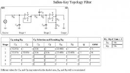
Re: Passing past Pass...
If you post over in the PassLabs forum, you have a better
chance of getting a response, as I only check here sporadically.
Also, what's to say? The XVR1 owner's manual has the
simplified schematics, and if you can't fill in the resistor values
from there, I refer you to the DIY op amp article, which pretty
much covers the rest of it. As stated before, these are simple
Sallen Key filters with variable everything. How you set up the
variability of the filters and the gain is your decision.
😎
moamps said:it seems rather pointless to continue this little 'I-dare-you' game started by Mr. Pass in the first place, since he has shown no intention of giving us feedback as to the validity and quality of our assumptions regarding HIS
If you post over in the PassLabs forum, you have a better
chance of getting a response, as I only check here sporadically.
Also, what's to say? The XVR1 owner's manual has the
simplified schematics, and if you can't fill in the resistor values
from there, I refer you to the DIY op amp article, which pretty
much covers the rest of it. As stated before, these are simple
Sallen Key filters with variable everything. How you set up the
variability of the filters and the gain is your decision.
😎
the views expessed are not those the management
Thanks Nelson. My sentiments exactly. I was not out to make a copy of the XRV1 but was just curious about how the resistor matrix might be done and the Q values for the discrete op amps. The Qs appear to be those for setting up classic Butterworth and Linkwitz-Riley filters and make perfect sense since these are well established and excellent filter alignments, used by most good speaker designers because of their excellent performance.
They DIY op amp article is excellent and these are very good and simple circuits. I don't know why more people in the forum are not building them. I kept all of this out of the Passlabs forum because I had planned to do a bit of hiking off the well established path and wasn't planning to call it anything with X or Zen in the name.
  I don't see how you can walk as it is with so many trying to ride on your coattails as it is. I had no plans to make a slavish copy after all it is called Do It Yourself Audio. Imitation is the sincerest form of flattery they say........Thanks for the road map for an interesting journey. I'll try not to get too lost. I feel that I have a pretty good sense of the direction in which I wish to go and as well as how to get there.
For information on the Linkwitz-Riley crossovers:
http://www.linkwitzlab.com/filters.htm#2
http://www.linkwitzlab.com/filters.htm#3
For those that want play with an online filter design program to do Butterworth filters:
http://beis.de/Elektronik/Filter/ActiveLPFilter.html#Parameter
Thanks Nelson. My sentiments exactly. I was not out to make a copy of the XRV1 but was just curious about how the resistor matrix might be done and the Q values for the discrete op amps. The Qs appear to be those for setting up classic Butterworth and Linkwitz-Riley filters and make perfect sense since these are well established and excellent filter alignments, used by most good speaker designers because of their excellent performance.
They DIY op amp article is excellent and these are very good and simple circuits. I don't know why more people in the forum are not building them. I kept all of this out of the Passlabs forum because I had planned to do a bit of hiking off the well established path
and wasn't planning to call it anything with X or Zen in the name. I don't see how you can walk as it is with so many trying to ride on your coattails as it is. I had no plans to make a slavish copy after all it is called Do It Yourself Audio. Imitation is the sincerest form of flattery they say........Thanks for the road map for an interesting journey. I'll try not to get too lost. I feel that I have a pretty good sense of the direction in which I wish to go and as well as how to get there. For information on the Linkwitz-Riley crossovers:
http://www.linkwitzlab.com/filters.htm#2
http://www.linkwitzlab.com/filters.htm#3
For those that want play with an online filter design program to do Butterworth filters:
http://beis.de/Elektronik/Filter/ActiveLPFilter.html#Parameter
Attachments
moamps said:
Mods,
would you please replace the old schematic I posted 5 posts earlier with this one. You can then disregard this post.
Regards
Done
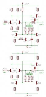
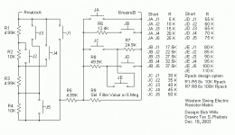
Some guy named Tex sent me this schematic for Yet Another Resistor Network. I think he felt sorry for me after my initial efforts. This spin of the Y.A.R.N. has 26 possible crossover frequencies for each capacitor in the capacitor matrix (actually many more if you parallel two or more caps in setting the capacitor matrix jumpers) It is programmed with two dual row 10 pin 5 position 0.1 inch pin headers and two jumpers*. JA to JE are for the coarse adjustments and J1 to J5 are the fine tuning settings. By changing A to C to D to E jumper positions and then sequencing the J1 to 5 jumper for each letter jumper chance you can go from 5 K to 100 K ohms in 5 K steps for twenty frequencies with a very easy programming sequence**.
If you care to change both the A B C jumper and the 1 to 5 jumper for each step you can go from 15 K to 40 K in 2.5 K ohm increments. The programming for this mode is more convoluted and is only for super fine turning after the simpler 5 K increment sequence. You should be able to dial it in very close to the exact frequency you want with a few values of capacitors in the capacitor matrix.
R9 is a DC path for the gates of the jfets in case all the jumpers get pulled. A couple of terminals across R9 will allow you to temporally wire a pot in place of the resistor matrix if you want to do some quick tuning. ONLY the J1 jumper will be installed. R5 will prevent shorting the circuit at the minimum setting for the external pot. Disconnecting the pot after the desired setting, measuring it's resistance and adding 5 K ohms to the resistance of the pot will allow you duplicate the setting with the resistor matrix where it will stay put and not get bumped by your children. Alternately purchasers of preposterously priced parts can solder the correct value across the resistor matrix inputs if two terminals for this are included in the PCB layout. This will allow one to bypass the resistors and jumpers after the desired setting and corresponding resistor value is determined. R1 to R5; R7, and R9 can be replaced by SMT R packs if space is at a premium in the PCB layout. Several resistors in parallel allow the use of standard values more easily available resistor pack. There are no shared R packs between filter sections and that should ease the PCB layout a bit.
This circuit is public domain and it's use by anyone who wants it is encouraged (yes even him......) And yes, I am sure about that! Tex told me so in his Email, or I would never post it. He assured me that he has no intent of changing his mind.
* Allowing one to hold the jumper in one hand and count the fingers on the other hand. BTW There is absolutely no truth to the rumor that one must remove both shoes and socks to program the Passlabs unit.
** i.e.. B1 B2 ect. If you have trouble, and you grandma plays Bingo, she can explain it to you if a jiffy.
Merry Christmas to all and to all a good night.
Fred
If you care to change both the A B C jumper and the 1 to 5 jumper for each step you can go from 15 K to 40 K in 2.5 K ohm increments. The programming for this mode is more convoluted and is only for super fine turning after the simpler 5 K increment sequence. You should be able to dial it in very close to the exact frequency you want with a few values of capacitors in the capacitor matrix.
R9 is a DC path for the gates of the jfets in case all the jumpers get pulled. A couple of terminals across R9 will allow you to temporally wire a pot in place of the resistor matrix if you want to do some quick tuning. ONLY the J1 jumper will be installed. R5 will prevent shorting the circuit at the minimum setting for the external pot. Disconnecting the pot after the desired setting, measuring it's resistance and adding 5 K ohms to the resistance of the pot will allow you duplicate the setting with the resistor matrix where it will stay put and not get bumped by your children. Alternately purchasers of preposterously priced parts can solder the correct value across the resistor matrix inputs if two terminals for this are included in the PCB layout. This will allow one to bypass the resistors and jumpers after the desired setting and corresponding resistor value is determined. R1 to R5; R7, and R9 can be replaced by SMT R packs if space is at a premium in the PCB layout. Several resistors in parallel allow the use of standard values more easily available resistor pack. There are no shared R packs between filter sections and that should ease the PCB layout a bit.
This circuit is public domain
and it's use by anyone who wants it is encouraged (yes even him......) And yes, I am sure about that! Tex told me so in his Email, or I would never post it. He assured me that he has no intent of changing his mind.* Allowing one to hold the jumper in one hand and count the fingers on the other hand. BTW There is absolutely no truth to the rumor that one must remove both shoes and socks to program the Passlabs unit.
** i.e.. B1 B2 ect. If you have trouble, and you grandma plays Bingo, she can explain it to you if a jiffy.
Merry Christmas to all and to all a good night.
Fred
Attachments
- Status
- Not open for further replies.
- Home
- Amplifiers
- Solid State
- Active Crossover Activity thread