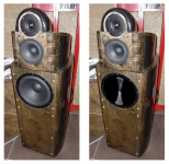
Looks like turning the basscab upside down moves the problem instead of solving it.

With the basscab normal I have the dip at 300 but after it stays good to about 110Hz. With the basscab upside down I get a huge shift at 180Hz.
With the basscab normal I have the dip at 300 but after it stays good to about 110Hz. With the basscab upside down I get a huge shift at 180Hz.
Bottom woofer placement is still cleaner (from a timing perspective) than the woofer up even though setting were not optimised for this woofer placement. Optimising might get it in line even more. I hadn't noticed something strange in the FR graph, though there was more output there (ground mirror) which also accounts for the time delay somewhat.
I asked for these plots to see what this one would show us, using both together (two woofers in one cabinet) could average out the problem areas, but probably will not solve all of it.
In the bottom woofer plot, did you EQ the FR back to flat prior to taking this measurement? It seems we see an average of the woofer plus it's floor reflection that determines the delay at 180 Hz. It would still be my favourite with a one woofer solution, compared to the alternative.
Looking shared rephrase file post 137 that make the base for DSP correction show the problem when compared to manufacture datasheet, probably its right in not try to correct the null in amplitude domain but then we got to live with it at present. Regarding APL_TDA being a measurement performance plot at listening position think if you move sub forward to one of the two points shown in below it start looks pretty good.
Attachments
I had these in mind for the woofer at ground level:
That would be what we're looking at in APL plots, right?
That would be what we're looking at in APL plots, right?
Here is another thing discovered looking at post 137 Rehase file, please don't blame me going in small shoes 🙂 wesayso is the one that knows quality-devil is in the details.
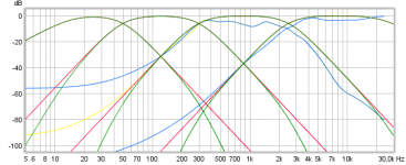
When summing audio band out of say two relative wide textbook band passes they sum perfect flat and coherent phase, but often get in trouble when going 3-way or 4-way dividing of audio band because each band pass gets so narrow and many of the drivers end in the totally sum when we look them down deep can see they multiple overlay each other. Example is below where the red curves is textbook target LR 4th order at 50/300/2500Hz and if we sum them they sum non flat because they so narrow and multiple overlay each other down deep. Green target curves is same XO points and right in it sums flat with coherent phase because they have sidebands added into calculation, example sub has besides its real LP slope at 50Hz also added a LP 300Hz slope plus a LP 2500Hz slope plus a LP 22000Hz stop-band slope.
The two blue curves is mid and tweet correction for Achilles-speaker and can see in lack of taps or the type of windowing that they miss correct steepness. In that we have problems in 100-300Hz area suggest try up the 800 taps for mid to 1600 taps and/or change also windowing type to see if 200-300Hz area then will change some, and same could be done for tweeter in double its 150 taps to 300, yellow curve is example of improvement up 1600 taps for mid. If there absolut is not more taps to drain from DSP then nearly same effect could be corrected add a 1st or 2nd order HP filter (at 120Hz mid / at 870Hz tweeter) either at line level or as traditional XO filter.
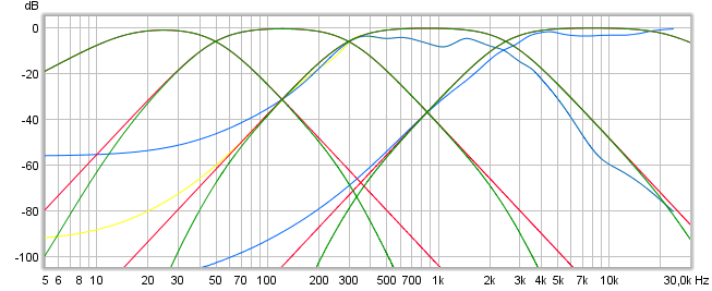
Attachments
Last edited:
@ weysayso: If you look at the relative distances to the listener, optimising time at 1m for woofer up top should be better at 3m listening distance with woofer at bottom then at top. It does play louder with woofer at bottom.
Yes that spl graph is what we are looking at with APL_TDA.
@ BYRTT: I only have 1023 taps per channel max, but I'll try to optimise the FIR correction below -40dB. Would using brickwall filters help? Haven't experimented with those yet.
I got the wood for making the ceiling islands and extra damping panels behind the speakers so I'll be focusing on making these the coming days.
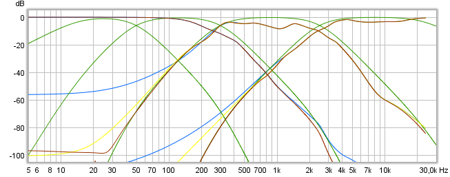
Okay seems pretty easy then to simply open up all 1023 taps for tweeter and mid channels, that gives below improved yellow curve compared to blue. The three blue curves are what you have now and the three brown is the three channels running full 1023 taps plus their side band partners XO points included. As example that means mid besides its primary 300Hz HP LR4 and 2500Hz LP LR4 also have 15hz HP BW2, 50Hz HP LR4, 22kHz LP BW2.
In past had some non documented subjective brickwall filter exercises and while it works don't think its a champ in long run, also POS recommend rather go very high order LR, but thinking is brickwall could perform great in ala Dunlavy symmetric setup or mayby also synergy horns as long as there is symmetry around a center : )
Have best fun creating hardware room EQ.
Attachments
Once you get past 40 dB down, the effects won't be as big on the total sum. The room additions in a normal room are way more destructive in phase at these frequencies.
That means that things like passive damping can help a lot to get better results requiring less correction.
Anything you're allowed to solve that passive way will help. Get out a damping panel to hunt them down and know where the problem spots are.
The upside down woofer bin has advantages over the original position, yet a setup with 3 smaller woofers might do even better. Mainly by not having the reflections the same between each of the 3 and therefore averaging out some of these room anomalies. You also got to stop somewhere.
Personaly I'd hunt down the difference in the right channel at 90 Hz, to make it more in line with the left side. Possibly could be done passively.
The current APL plots posted would have me hunt down the woofer/sub integration before anything else. You have 2 subs, right? Can you sent a different signal to each one? Not getting at Left or Right signals, but differences in SPL level at frequencies. Make each of them work in their strong areas, and try to get the timing correct.
I'd also use no FIR correction at all to find the answers. Only the normal crossovers. If you get that right, correct the crossover phase. Right now it will be very hard to interpret what does what.
Last edited:

Hi Draki those look really nice based they being taken at about 2,5 meters, but without knowing your actual setup am i wrong in thinking where is the direct relation to this threads build.
So building and mounting the ceiling islands took a lot longer then I expected (other fun stuff came up and I decided to also incorporate RGB led lighting) but they do look great 🙂

And T20 times dropped significantly, new measurements with basstrap, damping behind speakers and islands in black.

And T20 times dropped significantly, new measurements with basstrap, damping behind speakers and islands in black.
The current APL plots posted would have me hunt down the woofer/sub integration before anything else. You have 2 subs, right? Can you sent a different signal to each one? Not getting at Left or Right signals, but differences in SPL level at frequencies. Make each of them work in their strong areas, and try to get the timing correct.
I'd also use no FIR correction at all to find the answers. Only the normal crossovers. If you get that right, correct the crossover phase. Right now it will be very hard to interpret what does what.
I have 2x15" drivers in 1 PPSL sub: http://www.diyaudio.com/forums/subwoofers/268803-15-plenum-ppsl.html
Cool man, nice new cieling islands and T20 time improvements.
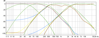
Regarding MW that throw perfect band-pass slope nearfield but at listening position seems to have such outs probably coursed by unfortunate distances to boundery's, being a pass-band covering 50-300Hz wonder what happens if you try to form a faceplate so it virtual is array of two MW not sitting in same height. Think if you try it out measure as is now but only measure that particuler band-pass (other 3 pass-bands disabled) nearfield and at LP, then mount a faceplate and DSP calibrate until its nearfield curve overlay with curve as is now and then finaly look if there's improvement at LP.
Regarding MW that throw perfect band-pass slope nearfield but at listening position seems to have such outs probably coursed by unfortunate distances to boundery's, being a pass-band covering 50-300Hz wonder what happens if you try to form a faceplate so it virtual is array of two MW not sitting in same height. Think if you try it out measure as is now but only measure that particuler band-pass (other 3 pass-bands disabled) nearfield and at LP, then mount a faceplate and DSP calibrate until its nearfield curve overlay with curve as is now and then finaly look if there's improvement at LP.
Attachments
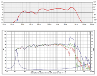
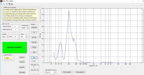
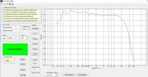
My apl_tda demo license ran out but I did measurements with REW for the 3 positions and with the basscab normal and upside down.
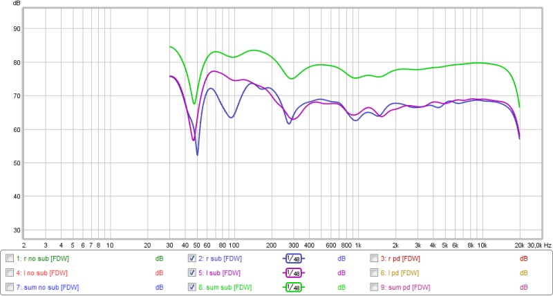
Left + right speaker averaged out over 3 positions. Red is basscab upside down

Doesn't looks so bad SPL wise. 5dB difference at 300Hz, 2dB at 100Hz
For the center position

I'll play with the timing of the woofer a bit to see if I can fill the gap up a bit, it's about 5dB now.
If I can find a quick and dirty way to make a faceplate I'll try to measure.
Left + right speaker averaged out over 3 positions. Red is basscab upside down
Doesn't looks so bad SPL wise. 5dB difference at 300Hz, 2dB at 100Hz
For the center position
I'll play with the timing of the woofer a bit to see if I can fill the gap up a bit, it's about 5dB now.
If I can find a quick and dirty way to make a faceplate I'll try to measure.
Last edited:
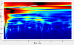
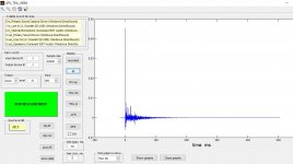
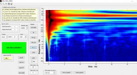
^That looks like a cancellation from the floor. Too sharp to be a timing error. Measure at various distances to see if it moves. Don't use eq!
The woofer is on the floor now (center 14.5cm from floor) and the timing is optimized for basscab normal at 1m tweeter height. It's not unreasonable to think the dip might shrink a bit with a bit of tweaking with timing is it?
...It's not unreasonable to think the dip might shrink a bit with a bit of tweaking with timing is it?
If its just a matter of tweak timing, think if you load the isolated curves for MW and MID passband each presenting nearfield verse LP and share them here will make it easyer to see if each of pass-bands position in space have isolated errors nearfield verse LP before summed.
Last edited:
Do you measure with a timing reference? Many ways to line them up perfectly.
I agree with BYRTT... it will show if it's a summing problem or the environment.
I agree with BYRTT... it will show if it's a summing problem or the environment.
@ Wesayso: I don't use a timing reference
So I played around with timing but could't get the dip smaller. (you were right Juhazi 🙂 ) I then tried some different crossover points.


All in all not too much difference, SPL wise about 2.5dB. Low male voices do get stretched a little in comparison to basscab normal, so I don't really want to raise the crossover point even higher.
So I played around with timing but could't get the dip smaller. (you were right Juhazi 🙂 ) I then tried some different crossover points.
All in all not too much difference, SPL wise about 2.5dB. Low male voices do get stretched a little in comparison to basscab normal, so I don't really want to raise the crossover point even higher.
- Status
- Not open for further replies.
- Home
- Loudspeakers
- Multi-Way
- Achilles FIR 4-way