eh
heya bud yeah i plan to make some plans so to speak lol its easy enough to build and looks great, the pics dont do it justice nor does the protective coating for now, but anyway we will see soon how it looks finnished and also how it performs.
Trev
heya bud yeah i plan to make some plans so to speak lol its easy enough to build and looks great, the pics dont do it justice nor does the protective coating for now, but anyway we will see soon how it looks finnished and also how it performs.
Trev
Cool! I contemplated buying one of those LCDs, but being me I decided to wait for someone else to try it first...
eh
yeah i did too at first but i got one finally and i thought why not lol anyway there a few with problems there are a few faulty ones out there as lilliput has a crapy QC, the one i have worked fine but in vga it didnt have red colour, i contemplated the warranty and the guy was happy to exchange but it means more time and postage so i took a look at it my self, i fixed it within a couple of hrs following the pcb traces and seeing wich wires are for what in vga and tracked down the red channel, it turned out it was a shitty pcb where as the red channel was shorting to the ground, just a glitch but bad QC, its all fixed now just a trimming knife did the trick but from what ive read from others in mp3 car forum who have bought one they also had trouble with their lcd mainly being the touch screen module not so much vga nor video in, the one i orderd was a non touch screen too so i thought i tell u that, i think it would be abit hard to touch my screen as it being in the projector lol, it would be nice to make a projected image touch screen or a laser pointer touch screen on a projected image though.
Trev
Size
Hi Ace... whats the size ouf your design ?
I'm very interested on building such a nice projector to i've got an 8" lcd panel (ripped out from my ASK Impact 21)..What lens do you use ?
Thanks
Bernhard
Hi Ace... whats the size ouf your design ?
I'm very interested on building such a nice projector to i've got an 8" lcd panel (ripped out from my ASK Impact 21)..What lens do you use ?
Thanks
Bernhard
neversaid
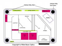
heya there bernhard, the sizes are 50cm length or long, 13.2cm hieght by 37cm deep i could have made it a tad smaller but i wanted to utilise a nice sleek look into the design like a nice hight to size ratio, as it is things in there will be quite tight for room and atleast there is room for it to brethe, the side is made of 1 peice of plexi, it will be bent via a heat gun to make the rounded corners, it will sit in a grouve i have not yet routed out and there should ba a 10mm overhang from the edges to the side peice, i thought that to give it abit more of a pro look, i got my infocus lp220 today and that has a 6inch svga lcd in that so ill be making another one soon similar to this one with the 6inch lcd, basically for your 8inch lcd the unit will be the same size just abit taller but that will depend on what harware you will have to use with your lcd.
Trev
Lenses
Hi Ace,
thanks for your fast answer. I'm very pleased about the size, its awesome.. really !! I like your design, and think i'll build it the same way. My ASK impact has got an 8,2" LCD Panel, i 2 fresnels, and some optics of an old Sliding-Projector. And i have got an 400W 32V Halogen Lamp. I managed it to cool the lamp down in it's case that is only produces about 80°. If i use a glas between Lamp and LCD (yeah and there's also a space between lamp and LCD, i think i've got no temperature problems.What type of lens you use ? Where it from ? I've got the change to get some extra produced optics from a big local firm (It's called Heidenhain in Germany).
So on tell me what you think. I'll be very pleased if you write perhaps a short review about building small projectors for my homepage..
www.virtuel-blue.de/diyprojector
Greets
Bernhard
Taking Shape
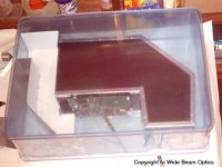
Well here is the next 2 pics on the progress, ive been busy latley so things are abit slow, ive fabricated the sides and cut the grove for the bottom plate, in the next 2 pics you will see how its starting to take shape but the protective covering still looks an eye sore lol, but aleast you get the idea of the shape and how it will be asymbled.
Trev
Attachments

Well im back into it again after waiting for my darn light to get here, its held me up from the whole project even though i have done small things here and there and rounded up some electrical plugs and relays and so on for doing some heavy modding on the main controller board, the inverter will be turned off completley without afecting other parameters of the controller and as the inverter uses an estimated 800ma i have power to play with for other things, 1 being a main power relay turning off and on with the lcd remote thus enabling all of the projector to get turned on and off with the remote, another modd is a standby power led and a power led, the one thats on the front buttons pcb only puts out 1v wich isnt enough for a standard 2mm super bright led so a modd is in order for that, to modd this once again a relay, but a micro relay, ive followed the circutry and found a 3.5v power source that is on all of the time, now with a small relay conected to the 12v inverter power when the lcd is off ill wire a led to the side of the relay that is in the closed circut posision, that will be for the stanby led and it will be enabled to be on, now when u turn on the lcd the relay turns on, the closed circut becomes open and the other side of the relay circut becomes a closed circut and that will turn on the power led, just small things like this i have been fooling with and working out in my spare time not that ive had too much of it latley but later on ill make a few audio circuts and timing circuts for the fans to be powerd on for 2mins after power off to cool things alittle faster and also a small timing circut to flash the stanby light for an indication when the light is warming up and also for a hot restrike time so i can have a indication when it is safe to turn on the projector if power does go out, i have 3 inputs, all can be conected at the same time, i have video1, video 2 and vga mode, they are controlled via the remote, i also have a audio in although usless for me and a audio out, a small modd i might do later on in the near future is to have a vga out so a monitor can be conected to the projector as well as the projector running on vga, in the last day ive been fooling with my light, as im trying to make the projector smaller ive decided to focus on making the light unit smaller and added abit more tech and thought in the design but ill still be using my honeycombe cooling as it works so well, in the pic below it gives u an idea on what im doing, the hot air will be sucked out from the outer of the pyramid (another thing that ive decided to impliment into the light engine), through the light box to the outside of the case, ive run a few rough tests and with a sealed light box system the fan has plenty of power to get the air flowing, remeber this is just to remove excess heat and to cool the light box enclosure, there are no cyclonic winds in here about 24cfm to be exact and with a mh bulb pushing air onto it is risky so ive decided to suck it, the air also wont be freezing cold as the air that comes into the light is from other sources first that are less hot so it works out well for the saftey factor of running the mh with an airflow, the honeycombe system is somthing that ive designed in the last 3months while i had a quiet period, basically cool air runs through small holes and the honeycombe is cooled, this way it acts like a heatsink, the heatsinking is not for the bulb, it is for the outer light box temperature to keep cool and it works, with a test halogen in another system i made up similar to this i managed to get the outer temp of the light box to just warm to the touch, it was nearly cold and thats on a halogen so with a mh its more then suficient, the louvers are well for the obvious to stop light comming out of the fan and that works great, as they are alloy they help to dissipate heat so once again another factor for cooling even further, in the pic u will see where the air comes from and where it goes, i havnt drawn in the pic the mounting plates that butt upto each other, the one that will be atached to the lcd and mirror unit will be pernament thus meaning it stays there while bulb change is in order, it will also hold the condenser, the second plate will butt upto the first and that will carry the light and reflector and fan, they will be made to butt against each other with a guiding system and a seal, to take the light out, 3 screws will be undone on the lcd unit at the top then the 4 screws that hold the fan into the outer shell of the projector, then all that is required is the light unit to get lifted out vertically and disconected from power via a molex, anyway thats about it for now ill keep u guys posted on progress and hope to have some more progress pic's soon.
Trev
Trev
ace i must say thats gotta be the best looking pj i have seen on this fourm GOOD FU*IN JOB man 
yes i doooo love the plexi look 😀 something about being able to see the components inside that turns me on
cant wait to see that bad boy in action
yes i doooo love the plexi look 😀 something about being able to see the components inside that turns me on
cant wait to see that bad boy in action
cruser
WHOA! thank's cruser, i wouldnt say its the best though, i would say its probally a first, a first being a first small lcd type projector made out of plexi totally see through, yours is still the best bud in the larger lcd range made out of plexi😀, there is somthing about plexi that makes it so sexy seeing all inside of a unit, but i also see the plexi as good as its internals, in your design i must say the internals look hot!! in mine hmmmmm we will see lol, as u know cruser no competition in here just personal preference and construction tecnque, i cant wait to see your new one, that will be one kick *** machine!!!!
Keep up the good work bud
Trev
suuuuure no competition  ....
....
....lol j/k 😀 Anyways, yah, just got two words: sexy beast ....does it got a name =p hehe. All i know is, i got first dibs on.... (u know what im talkin bout ace) 😉 lol
........lol j/k 😀 Anyways, yah, just got two words: sexy beast
....does it got a name =p hehe. All i know is, i got first dibs on.... (u know what im talkin bout ace) 😉 loljj
hehehehe how's it bro? thanks for the nice coment's, hmmm what name should i give it? ahhhhh i know how about up yours? lol jk😀
hehehehe how's it bro? thanks for the nice coment's, hmmm what name should i give it? ahhhhh i know how about up yours? lol jk😀
Ok well the time has come to show some pictures of my light box progress, although not finnished totally the light engine is over half complete and the pics you are about to see are of the unit just sitting together, i should have it finnished today time permitting and that will be part A of the light engine complete, there has been alot of thought into this light box, bulbs go bang, cause damage and also are touchy with a cold environment with dirt and dust, also i needed to make the light box cool to the touch to eliminate any excess unwanted heat and make it also light proofed, well i have done all of that and to my suprise it works better then i had originally planned, i get no light out of it at all, nothing out of the fan (as in light) and the box is remarkably cool, also i get a steady air flow and the box its self could take a large fire cracker in side without any damage, anyway here are the pics, the first pic is of the main secrets behind the design, it is the interior unit, u will see the louver, and the honeycombe holes, there are 427 holes per side of the unit and i drilled them all by hand, yess thats right 854 holes in total!!! (with an electric drill of course) they are 3.2mm holes placed at 5mm apart, also in this pic it hasnt had its final paint job so u will see some of the new alloy. If u look also u will notice that it has one bracket up one end, that is for the light socket and this is part of the design, the other end is designed to be left open and to take the force or concusion of an exsploding bulb, it can be easily bent back into place if it gets bent out far and is about the right tension to take a bulb blow without bending much at all but also taking the full force.
ok here is another shot , here u can see the louvers better and they are on both sides.The tri square u can see in the background is for a size comparison same with the pen, drill bits, and other crap laying around.
ok now we are getting somwhere, here is the internal unit in its gleaming new coat of paint, oh and look at the back, thats the outer enclosure to house the internal unit, in this pic the internal unit had also its end mounts added and are held on by a right angle bracket at the bottom, this will fit into the outer casing with a perfect gap all of the way around the internal unit for the airflow, the end brackets also block the air from coming in from the ends as its only suposed to come through the honeycombe and vents. The large hole in the outer casing you can see is for the fan (probally u guessed that already).
ok here is another shot with the outer end caps for the outer casing of the light box, with using 2 end caps incorported with the inner we now have a double insulated side for the box and it stays cold, the rest of the side (top and bottom sides) get just warm to the touch about 10deg c as there is hot air moving through it but no heat radiated at all, in this pic is the parts that will make up the finnished part A light unit.
- Status
- Not open for further replies.
- Home
- General Interest
- Everything Else
- The Moving Image
- DIY Projectors
- Ace_3000....pictures of Projector?