Trevor White,
ACE Bass is not MFB because there is nothing to sense the motion of the cone and no feedback loop with large loop gain.
-->
ACE Bass is firstly based on nullifying the series resistances and inductance of the voice coil.
There is something coming from the voice coil of the loudspeaker which is sensed : it is current which in itself contains information about the motional impedance. Motional impedance reflects the voice coil velocity, it is not extracted in Stahl's circuit but is it really ignored for the definition of the negative impedance of the amp ?
There is always a controversy to determine if negative impedance applied to a driver is, or is not, MFB (for example Watkinson vs McLaughlin in british Electronics World).
Velocity feedback using a Voigt bridge and current sensing used to generate negative impedance are quite similar circuits and the results for closed boxes are quite similar too in the reduction of distorsion, I think.
Very nice, short and informative thread. Please let me add my contribution to it.
1.
The conventional Voltage-Driven speaker exhibits a straight dependency to the BL factor. If B drops by 15%, then the acoustic output drops by 15%. This is the problem, and this is why people want more elaborate speaker driving schemes.
2.
The Speed-Follower driven speaker exhibits a reciprocal dependency to the BL factor. If B drops by 15%, then the acoustic output increases by 15%. Distortion again. That's plain normal, as Speed-Followers are those systems monitoring the voice coil voltage, applying global feedback from it. They require an extra coil as pickup, or a dead-coil voltage cancellation scheme. The dead-coil voltage cancellation scheme implies measuring the instantaneous current in the coil, and knowing precisely what's the coil resistance and the coil inductance. Anyway, the voltage coming from the coil will be equal to B.L.V with B=magnetic field, L= coil wire lenght, V=coil speed. In a feedback system, if B happens to decrease, the system will react by increasing V, the speed. As the frequency is the same, it has no other choice than increasing the amplitude.
3.
There is another driving method between those two extremes. It is called "impedance matched drive". You implement it by building a Speed-Follower, then feed the audio signal using a parallel CRL network. Such parallel RLC network materializes the reflected impedance of the speaker that's located at the secondary side of a transformer which is the BL process. At the secondary side, for a closed box system, the series LRC circuit is composed of the moving mass, the air damping, the compliance. The BL system gets seen as a transformer. You know that a transformer is reciprocating its load impedance. This explains why the matching impedance located at the primary side must be a parallel CRL network. From the general theory, you know that once you get "impedance matched", that the energy gets transferred in an optimal way, with minimal losses. You also know that your BL transformer is not a lossy component. Thus the energy gets transferred in an optimal way, with minimal losses, even when you change the transformer ratio. Which is the BL. From there comes the BL independency in the "impedance matched drive".
So it a nutshell, yes, as soon as you see a speaker drive scheme measuring the current, you may hope that the guys having designed it did their homework, and duly calculated all resistors values and capacitors values for implementing an "impedance matched drive". Which will then provide the required BL independency for ironing out distortion, even when very close to the Xmax.
Don't make me say what I didn't say. When BL is changing, like being nonlinear, the circuits "detunes" which means that the RLC values are not anymore matched. This way the energy transfer departs from being optimal, this way you get acoustic amplitude variations, and this way you get distortion. But it's a 2nd-order effect. The main goal of ironing out distortion remains fulfilled.
I would thus say that the "impedance matched drive" is a kind of MFB, really and scientifically featuring a THD reduction.
Are you interested in a few LTspice simulations illustrating this?
Steph
Last edited:
Wow, I thought everyone had forgotten about this. I read about it years ago but never saw anything come out of it. Looks like it is time for re-reading.
I am all for any spice models. Much to learn.
I am all for any spice models. Much to learn.
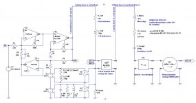
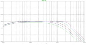
Here are the LTspice simulations. Please read the .pdf.
Attachments
reconstruction
Do any of the entities who implement systems like this "impedance matched drive", measure voice coil and magnet temperature?
.
Rdc of copper rises by 3800 PPM/° C
Magnet Bh max also drops significantly with each degree of temperature rise, of course the actual number depends on the magnet type.
Even thermal expansion of the structure may change the air gap.(probably not an issue with loudspeakers)
.
I work in an R&D lab on machines with a linear alternator quite similar to a loudspeaker motor, but with moving rare earth magnets.
We have been able to use the current waveform to infer (we call it reconstruction) the amplitude and position of the alternator, but it is not possible to accurately infer DC bias of the position (probably not an issue in speakers).
.
We use a DSP to do the calculations and all that is required, other than starting conditions (Rac, Rdc, Inductance and magnet properties), is the temperature of the coil and magnets.
.
.
Also, why when I try to Cut-N-Paste subscript (such as Rdc, Rac and BH max) , does this forum randomly change what words have subscript😕 Oh well I give up.
.
Anywho, I can see that there may be many ways to sense and correct speaker cone, or at least voice coil motion.
Dave
SNIP.............
The conventional Voltage-Driven speaker exhibits a straight dependency to the BL factor. If B drops by 15%, then the acoustic output drops by 15%. This is the problem, and this is why people want more elaborate speaker driving schemes.
SNIP.............
And
So it a nutshell, yes, as soon as you see a speaker drive scheme measuring the current, you may hope that the guys having designed it did their homework, and duly calculated all resistors values and capacitors values for implementing an "impedance matched drive". Which will then provide the required BL independency for ironing out distortion, even when very close to the Xmax.
Do any of the entities who implement systems like this "impedance matched drive", measure voice coil and magnet temperature?
.
Rdc of copper rises by 3800 PPM/° C
Magnet Bh max also drops significantly with each degree of temperature rise, of course the actual number depends on the magnet type.
Even thermal expansion of the structure may change the air gap.(probably not an issue with loudspeakers)
.
I work in an R&D lab on machines with a linear alternator quite similar to a loudspeaker motor, but with moving rare earth magnets.
We have been able to use the current waveform to infer (we call it reconstruction) the amplitude and position of the alternator, but it is not possible to accurately infer DC bias of the position (probably not an issue in speakers).
.
We use a DSP to do the calculations and all that is required, other than starting conditions (Rac, Rdc, Inductance and magnet properties), is the temperature of the coil and magnets.
.
.
Also, why when I try to Cut-N-Paste subscript (such as Rdc, Rac and BH max) , does this forum randomly change what words have subscript😕 Oh well I give up.
.
Anywho, I can see that there may be many ways to sense and correct speaker cone, or at least voice coil motion.
Dave
Remember that for getting rid of the 1st-order BL dependency using the Matched Impedance drive, you need to know the impedance (and reciprocate it as source impedance) that's attached to the secondary of the BL considered as transformer.I work in an R&D lab on machines with a linear alternator quite similar to a loudspeaker motor ...
Like you I remember having read something about the "Matched Impedance" drive. Now I'm asking myself from where I got the idea of the "Matched Impedance" drive. Can you please help me finding publications about it?Wow, I thought everyone had forgotten about this. I read about it years ago but never saw anything come out of it. Looks like it is time for re-reading.
Today I went digging Wireless World, the AES publications and the US patents, and could not find a single line about the "Matched Impedance" drive arrangement. I read more than 100 publications. None of them explicitly exploit the "Matched Impedance" arrangement. Some US patents like the Yamaha AST patent US5031221 represents in fig.15 the negative LR and parallel positive CRL networks, but even doing so they avoid talking about the "minimal loss" theorem when the transmission medium gets impedance-matched, thus they omit the crucial BL independence considerations. They may do this on purpose, for not disclosing the most interesting feature of such arrangement.
Most patents I saw looked like revamped Voigt bridges and Maxwell bridges. I did some more LTspice simulations. Using simulations, a Voigt bridge or a Maxwell bridge translates into a "Speed-Follower". This means that with a Voigt bridge or a Maxwell bridge 1) the frequency response gets easily extended in the deep bass (1st-order lowpass -3dB at 20 Hz if you introduce the required -6dB/oct equalizing function), but 2) any BL nonlinearity will be reciprocated and certainly not cancelled.
Using LTspice, I found a very simple modification to be applied to a Voigt bridge or Maxwell bridge for improving them quite significantly. With such simple modification, the system tends to operate from 100 Hz to 1000 Hz as "BL invariant" with a reduced 1st-order sensitivity to BL. That's quite interesting and may explain why only a few commercial Voigt bridge and Maxwell bridge based systems could deliver both the promised deep bass extension, along with some useful THD reduction.
A nice idea would be to simulate the ACE-Bass and determine if, correctly adjusted, it tends to operate on an decent frequency bandwidth as "BL invariant" with a reduced 1st-order sensitivity to BL.
Attachments

Last edited:
Here are the .asc files in a .zip
Thanks for that.
Actually Baldin and I have used one of your older files to try to simulate the Acebass schematic given on the Forum. See attached the simulation files.
I never got it to work properly maybe about the lousy UCD400 model (balance 100k input (how is is changed when unsed unbalabced?), 35kHz bandwidth 2nd order LP filter and 20 - 100mR output impedance as can be seen in there AES paper http://www.hypex.nl/docs/papers/AES118BP.pdf)
Baldin discovered that we had to stick with the high resistors in the buffer/inverting stage BTW.
Any hope we can have some help on it?
M
Attachments
I will revert back to this thread after I have simulated ACE-bass on LTspice.
Please note I have created a new thread dealing with the "Matched Impedance drive". Such loudspeaker driving method, basing on an instantaneous current measurement, tends to annihilate the effects of BL nonlinearities from 10 Hz to 1000 Hz, without relying on an accelerometer.
See it here : http://www.diyaudio.com/forums/subwoofers/222249-matched-impedance-drive-advantages.html
Glad you published this (wouldn't do it as you did most of the work 🙂 ) ..Thanks for that.
Actually Baldin and I have used one of your older files to try to simulate the Acebass schematic given on the Forum. See attached the simulation files.
I never got it to work properly maybe about the lousy UCD400 model (balance 100k input (how is is changed when unsed unbalabced?), 35kHz bandwidth 2nd order LP filter and 20 - 100mR output impedance as can be seen in there AES paper http://www.hypex.nl/docs/papers/AES118BP.pdf)
Baldin discovered that we had to stick with the high resistors in the buffer/inverting stage BTW.
Any hope we can have some help on it?
M
When you say it didn't work .... what didn't work?
Still think it is a very useful and straight forward simulation tool 🙂 ..... would be nice to also have a version for a passive radiator box, and a passive radiator box, where the passive is actually a normal speaker, but where you can place e.g. a resistor over the voice coil.
The impedance of the power amp does not matter if you use the inverting amp in front of it and raise the input impedance to at least 100k, and as we discussed the gain in the inverting amp should be at least 10, for the combination of the inverting amp and the power amp to work more closely as an ideal opamp.
I tryed myself to change the 2 resistors R12 to 1M and R15 to 100k in my setup (see schematic post #26). First it made a really bad noise when starting up .... had to turn it off right away. Then changed R12 to 100k ... this resulted in sound but 1V DC on the output ... then I gave up for now ... cant really see why there is DC on the output as there are coupling capacitors all around! .... will investigate and try another power amp one of these days 🙂 ......
@steph_tsf there is no doubt that AceBass will reduce distortion, and can be considered a kind of servo.
Best regards Baldin
Feedback around the speakers.... the final frontier.
About everything that I can understand and which needs to be said about voice-coil MF was in the J. Acoustical Soc. Amer. in 1957 by Werner from RCA labs in Camden*. The ACE-Bass, as far as I can tell, is no advance on that.
Effect of a Negative Impedance Source on Loudspeaker Performance
For mostly narrow commercial reasons, lots of companies have filed trivial variants on Werner's patent (which itself is probably a trivial variant on work done in 1940s on current feedback amps). For a patent update and lotsa references:
Patent US8401207 - Motional feedback system - Google Patents
After Werner, I built a few MF amps and an out-board box that works with various amps and confirmed the benefits by some after-hours testing at Bell Labs. The benefits are substantial. But like with a lot of things, the worser the system the bigger the benefits of feedback.
The basic principle is this. When the cone moves, the sound comes out, roughly in proportion. Any time the cone moves, the VC generates back-EMF as a good replica of the cone motion. Any time the back-EMF is different from the signal, you've got distortion. You can also view the back-EMF as the varying impedance of the driver. So using feedback, we want the amp to act like the negative of that impedance and the cone motion will more closely resemble the signal. Unlike with super-low output impedance to facilitate driver damping, when you go negative, you want the amp to act with a negative impedance just as big as the driver... but the result is, of course, super-super-damping.
At resonance and for impulses, cones play the signal poorly and the back-EMF is way outta line. Also think about this: below resonance - and we are always talking only about sealed boxes when we are talking about motional feedback and woe to those who don't understand that - the cone also is not following the signal. So a little feedback will do great things at resonance, for impulse signals, and can extend driver output below resonance in sealed box.
Often you see just a single resistor between the driver and ground in order to produce a feedback (usually referred to as a current feedback resistor). That is a kind of bargain-basement version of putting the VC in a bridge, where the bridge attempts to be a simulation of the the driver/enclosure parameters**, save only for the back-EMF. So the goal of the balanced bridge is to nullify all but the back-EMF feedback signal. The better the model, the better the nullification.
Ben
*on this forum, change in VC resistance with temp is a major source of personal anxiety; not sure many worried about it in 1957 (or today) but it can be accommodated under the balanced bridge concept easily enough
** see previous footnote
Last edited:
... and we are always talking only about sealed boxes when we are talking about motional feedback and woe to those who don't understand that
Calling ACE Bass MFB, is maybe streatching it a littel. MFB as in the way used by e.g. Philips is servo drive, with the input from the motion (actually acceleration) of the driver.
ACE Bass and other negative impedance schemes are different. And contrary to servo it can be used for vented designs ... which is really one of the beauties of the system 😉
Best regards Baldin
Perhaps I don't understand ACE Bass. If the behaviour of the cone is used as feedback isn't it fair to call it motional feedback? Not sure if a purist would put accelerometer feedback in the same category because the feedback is mediated by a sensor making it a servo, but in a sense it also produces negative output impedance.Calling ACE Bass MFB, is maybe streatching it a littel. MFB as in the way used by e.g. Philips is servo drive, with the input from the motion (actually acceleration) of the driver.
ACE Bass and other negative impedance schemes are different. And contrary to servo it can be used for vented designs ... which is really one of the beauties of the system 😉
Best regards Baldin
Vented designs (and TL and TH designs) have sound output (at least in the broad region around resonance) where the cone motion and the sound output don't match. So motional feedback is correcting the cone motion but distorting the sound output.
Ben
Last edited:
Not sure what you mean .... that the cone motion and sound output don't match .... the come still moves the air in a vented design, and the port output is a function of the cone movement ... therefore correcting the cone movement/output by feedback will also have a positive effect on the port output.
Actually thinking it over, I think it would also be possible to use servo for a vented design, but you would need a filter which matches the correct cone movement for this type of design, meaning much less movement at the resonance freq. ..... a problem will be that Fs will change over time due to aging of the suspension ..... therefore needing calibration ....
Actually thinking it over, I think it would also be possible to use servo for a vented design, but you would need a filter which matches the correct cone movement for this type of design, meaning much less movement at the resonance freq. ..... a problem will be that Fs will change over time due to aging of the suspension ..... therefore needing calibration ....
Just above box/Helmholtz resonance, the cone starts extra movement and the port starts pumping out sound in phase.Not sure what you mean .... that the cone motion and sound output don't match .... the come still moves the air in a vented design, and the port output is a function of the cone movement ... therefore correcting the cone movement/output by feedback will also have a positive effect on the port output.
Actually thinking it over, I think it would also be possible to use servo for a vented design, but you would need a filter which matches the correct cone movement for this type of design, meaning much less movement at the resonance freq. ..... a problem will be that Fs will change over time due to aging of the suspension ..... therefore needing calibration ....
At box resonance, the box hinders the cone motion but a strong sound comes out of the port.
Just below resonance, the cone is again moving too much but the port is pumping out sound in opposite polarity so the total output is diminished below resonance at a terrible 18 dB/8ave (granted BR resonance is lower than sealed box resonance for the same driver, etc).
Thus the sound entering the room is not proportional to cone movement.
The stories with TLs and THs are only analogous but the conclusion is the same. And I had a shock when I saw the box with the tube vent above.
Can these box concepts be corrected with DSP? I think the complexity of doing so, if possible at all even in theory, is very great. Does anybody "correct" BR boxes now... other than post-hoc with REW?
By contrast, sealed boxes and infinite baffles fit the feedback model; OBs and dipoles sort of; horns sort of fit the model esp if they have sealed boxes behind the driver (like a Klipschorn).
As someone is sure to point out, the relationships of cone motion, cone diameter, frequency, weight of air, and sound output are not simple, but their relationship is very simple to linearize with filters.
Ben
Last edited:
on this forum, change in VC resistance with temp is a major source of personal anxiety; not sure many worried about it in 1957 (or today) but it can be accommodated under the balanced bridge concept easily enough
I'd like to learn more about what you say above regarding using the balanced bridge and how that somehow accommodates for Re increase with VC heating.
The reason I ask this, is I am one of those who has been interested in the ACE BASS concept in the past, and thought about how to track Re so that amplifier output impedance could be adjusted accordingly. My idea was/is to use a large and heavy driver oriented with its axis of motion vertically (e.g. cone facing the floor) and the to apply a steady DC current by injecting this into one of the amplifier terminals. The DC current will induce a voltage drop across Re that will change no faster than a tens-of-seconds time scale. One can use steep LP filtering to eliminate most of the modulation of the voltage. This should allow you to track the VC resistance, and temperature as well I guess. Using the data on Re, one can use a microcontroller to vary the feedback resistor (Rrs) that sets the amp's negative output impedance or something along those lines. The idea is that if you can closely cancel Re even when the driver's VC heats up and Re increases, then you can keep better control via ACE-BASS under those conditions.
I made up a bunch of SPICE type sims of this and it seemed to be doable but I never build a real circuit. Should I try it? Does this sound like something that might work? Should I take another look at the balanced bridge concept?
Last edited:
I'm not the one to talk about circuits in such distinguished company, but here goes my amateur thinking anyway.I'd like to learn more about what you say above regarding using the balanced bridge and how that somehow accommodates for Re increase with VC heating.
The theory of balanced bridge to derive feedback is to create a Wheatstone Bridge with the driver/box in one leg and a model of the box/leg in another leg (and two in-proportion resistors in the other legs). If the driver generates back-EMF, that unbalances the bridge and produces a signal which is, in theory, pure back-EMF(AKA the variable part of speaker impedance when in motion). Of course, it really isn't necessary for it to be pure back-EMF since other scraps of feedback are welcome too.
Can you model the effect of heating? I just sort of take that for granted it can be done with the components you can buy today and I see that creative persons like yourself have actually been trying to do it (I don't believe the effort is worth the prize, but I guess wiser persons do think so).
The advantage of getting heating into the picture using a bridge is that the bridge leg is a "scale model" of the driver/box and so you have more flexibility than you'd have trying to use light bulb filaments and other things which physically resemble VCs, although that is possible too.
I might add that I don't think it is worth fussing over balancing a bridge. Just grabbing a bit of back-EMF is such a big benefit, the niceties of balancing to nullify capacitance, inductance, resistance, heating gremlins, and other driver/box parameters are just icing on the cake.
Ben
Last edited:
- Home
- Loudspeakers
- Subwoofers
- ACE-bass amplifier design