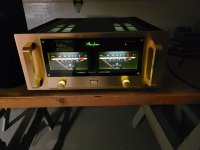
Finally completed my Accuphase, will all front panel leds and lights working. The Accuphase logo is ON when normal and flash in case of a failure. The meters also are turned off in case of failure, as the original. I had some problem to make the meters to work, first I had to figure out the included front panel pcb with its circuit for the lights, and the meters sensibility adjustments. Then I tried to connect the meter driver circuit but there was a constant dc offset at the output of the circuit, strange. Had a deep look at the meter drive circuit schematic and something was very wrong with the meter IC I had, they were counterfeit naturally... Found good ones on ebay, and this time it was making sense... Adjusted the board as per the service manual, and Voilà! a complete amplifier... See the short video showing the lights and meter moving...
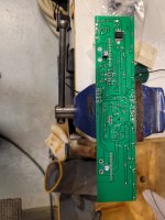
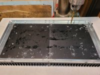
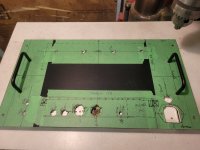
None of the functions indicator leds were included, the front panel was machined to received the leds, but no circuit, neither provision to install these leds was included. I had to make my own. The Front panel PCB was supplying only the power to the meter lightning led arrays. See the the back view of the included front panel lights and meter pcb.
SB
Attachments
Last edited:

This evening, just completed my second Accuphase P-7100, I hope this one is for me, the other, original clone chassis went to a friend that refused to let it go, it was too good... Since I cannot have ten amps at home (that's what my wife said 😉) I decided to sell it to him, but the sound was so good from this amp, that I missed it a lot.
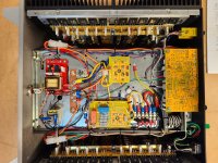
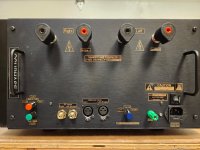
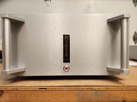
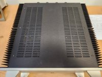
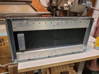
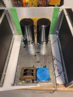
I decided to build a second one, but this time with a simpler to build (and less expensive) chassis from Hifi2000. I bought a 5U Dissipante chassis and modified it to accept the Accuphase pcb. The front has a simple Power-On temporary switch with led, press the switch and it flash at power-on, than turn-On once the speaker relays engage. If there is any fault, the speaker relays open, and the led flash (Faults are DC output and Over temp, the amp has current limiting circuit built-in). Simple and elegant. The front switch activate my own Power-On toggle circuit, with high power relay, better than the original simpler switch. The really expensive Furutech speaker binding posts were so good on my previous built that I had to use them this time again. I can't believe the number of high-end amp I saw with small, flimsy output binding posts. These are the real thing! As the other one I installed heat spreader bars on the heatsink to mount all the transistors.
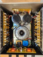
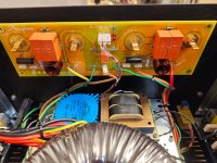
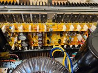
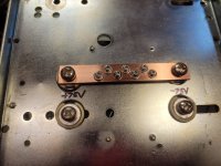
This time I'm using a custom built 1KVA Power transformer from 'James Transformers', great part, potted center, no buzz, great packaging, I'll certainly buy from James again. For the main power supply I'm using 47,000uF/100V big caps I had in stock, the other built uses 51,000uf caps, should work as well... Check the large gauge copper ground bus bar, that's a real star ground! The 5U chassis was just large enough to fit all the boards.
The measured specs are almost identical to the previous one as well. Listening session tomorrow...
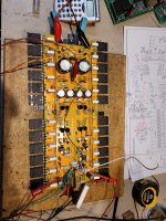
Check the built pictures
SB
I decided to build a second one, but this time with a simpler to build (and less expensive) chassis from Hifi2000. I bought a 5U Dissipante chassis and modified it to accept the Accuphase pcb. The front has a simple Power-On temporary switch with led, press the switch and it flash at power-on, than turn-On once the speaker relays engage. If there is any fault, the speaker relays open, and the led flash (Faults are DC output and Over temp, the amp has current limiting circuit built-in). Simple and elegant. The front switch activate my own Power-On toggle circuit, with high power relay, better than the original simpler switch. The really expensive Furutech speaker binding posts were so good on my previous built that I had to use them this time again. I can't believe the number of high-end amp I saw with small, flimsy output binding posts. These are the real thing! As the other one I installed heat spreader bars on the heatsink to mount all the transistors.
This time I'm using a custom built 1KVA Power transformer from 'James Transformers', great part, potted center, no buzz, great packaging, I'll certainly buy from James again. For the main power supply I'm using 47,000uF/100V big caps I had in stock, the other built uses 51,000uf caps, should work as well... Check the large gauge copper ground bus bar, that's a real star ground! The 5U chassis was just large enough to fit all the boards.
The measured specs are almost identical to the previous one as well. Listening session tomorrow...
Check the built pictures
SB
Attachments
-
 20241022_202024.jpg517.6 KB · Views: 147
 -
 20241022_201534.jpg740.3 KB · Views: 155
 -
 20241022_202012.jpg653.9 KB · Views: 160
 -
 20241022_202716.jpg646.4 KB · Views: 159
 -
 20241022_202756.jpg460.4 KB · Views: 143
 -
 20241022_203052.jpg593.7 KB · Views: 138
 -
 20241022_202020.jpg491.7 KB · Views: 158
 -
 20241022_202034.jpg700.9 KB · Views: 154
 -
 20240822_205347.jpg809.7 KB · Views: 154
 -
 20240904_155300.jpg473.3 KB · Views: 144
 -
 20240904_160353.jpg524.8 KB · Views: 133
 -
 20240808_140454.jpg508.8 KB · Views: 125
 -
 20240808_140500.jpg498.4 KB · Views: 128
 -
 20240806_180504.jpg819.3 KB · Views: 135
Last edited:
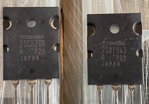
No, got the board set from www.yoycart.com. I can send you the link. It was 112U$ + shipping. PCB are a very high quality, 2mm, ENIG plated, etc... But keep in mind you need a lot of now obsolete 2SC/2SA transistors, most on the net are now fake. I got original ones years ago.
Also the final transistors are difficult to get. I think I bought the last set from Japan. I can sell the set if interested. You can get the service manual with all the schematics and BOM from internet. Got mine from www.hifiengine.com
Also as I said the Meter/protection PCB is incomplete, and you need a lot of info from me to make it work as I did.
So a great project, but now difficult to built because of the obsolete parts... and expensive.
For the record it is the best amp I ever heard so far.
SB
Thanks for the additional info SB.
I was looking at the P-7100 SM this evening. You’re right, quite a task to gather the original transistors for this amp. Not sure I want to get sucked into this monster.
You built a another beauty, enjoy it!!
PS: This time, don’t loan it out….. It might not come back again 😂.
I was looking at the P-7100 SM this evening. You’re right, quite a task to gather the original transistors for this amp. Not sure I want to get sucked into this monster.
You built a another beauty, enjoy it!!
PS: This time, don’t loan it out….. It might not come back again 😂.
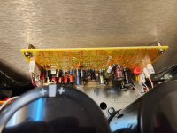
Here bottom view showing all the wirings. Power trnasformer is coming from a Rotel RX-1603 integrated, rated at 180W. Should work in this amp...
SB
I love your brilliant workmanship >Did the max. Power test using two 5R resistors, one per channel and in Dual Mono mode (same left signal on both outputs).
Got 39Vac, into 5R, both channels full power, or 304W!
AC input power was 970W…
should be enough to drive my Wilson Audio Sasha clone… We’ll see this afternoon
SB
but in my mind there seems to be some discrepancy between the capacity of the power transformer and your measured output power.
If the transformer is rated @ 180W, and you're measuring 304W output , where is the power coming from ?
With rails of +/- 75V you will surly get great transient power, but under continuous conditions I think the transformer is going to get very hot.
My real point being > I think your power transformer is under rated 😕
With a 'Super Dooper' transformer, +/- 75V can deliver significantly more power > meaning you are getting 'voltage sag' with your transformer.
I know but first I'll never drive my speaker at full power 😉. I never knew the rating of the recycled Rotel transformer I used in the first amp I built. I only knew the specs of the Rotel amp it came from. I would be surprised from the size if it was more than 1kVA at it was more than enough in actual used, and on the bench as well up to 4 ohms load. The comments you quote were for my first amp built. The second one is using a 1kVA transformer.
When I tested the second amp (the current one discussed) with my power dummy load of 8 ohms, the power supply barely drops at all. Output was 40Vrms before clipping into 10 ohms, or 160W, way over the specs of 125W/8 ohms. Probably at 2 ohms it may be an issue, but at the current listening level, and with the rather high efficiency speakers I have I may used the amp with 5W-10W at the most, so plenty of power reserve for me. The transient response of this amp is fantastic, probably due to the ample power reserve.
The original specs for the transformer was 1.5Kva in the literature, but it is probably to meet the 1 ohms at 1000W specs. For this last specs they say: ''Apply only to operation with music signal'', meaning transient signal, not continuous power. Original max power is 500W/2 ohms per channel, that is about 15.8A per channel at this power, a 1.5KVA transformer, with dual 55V secondaries, gives about 19Adc of current. So their big 1.5KVA transformer was up to the task for this incredible power. A 1kVA transformer produces only about 12.8Adc, ample power for 4 ohms, and even lower transient impedance.
Anyway I won't need that much power and the much larger 1.5KVA was not fitting into my chassis, the 1Kva just fits nicely, so 1KVA it is I'm afraid. And the amp is heavy enough as it is 😉
SB
Last edited:
COOL >
Sorry for a misunderstanding on my part.
AND, you're going to have heaps of headroom when it comes to 'real world' music listening.
GREAT WORK 🙂
PS.
My power amp has a 1.5KVA transformer and delivers 700W per Ch. into 2 ohms.
Sorry for a misunderstanding on my part.
AND, you're going to have heaps of headroom when it comes to 'real world' music listening.
GREAT WORK 🙂
PS.
My power amp has a 1.5KVA transformer and delivers 700W per Ch. into 2 ohms.
I was just quoting Accuphase specs, their transformer may be only 1.2KVA for the dual 55V secondaries, it has other secondaries so they need to be subtracted from the total 1.5KVA, we can only guess. 1.2KVA seems about right to get 500W into 2 ohms as the original, but maybe only 330W into 2 ohms with a 1KVA transformer. I'll be very happy with only 330W into 2 ohms 😉
This amp can also be bridged, or dual mono, so plenty of power configuration. I'll use only the stereo. The power transformer itself is 8.8Kg or 17.6lbs, heavy enough as well.
SB
This amp can also be bridged, or dual mono, so plenty of power configuration. I'll use only the stereo. The power transformer itself is 8.8Kg or 17.6lbs, heavy enough as well.
SB
Last edited:
Great work SB. Have you ever heard any of the Accuphase pure class A amps such as the A60 or A65? I’m just wondering how they sound in comparison to the P7100, apart from the obvious power difference - ?
https://shop102543689.taobao.com/
I think this is the original "Nori" offer; got a 2810 IC-based clone PCB set and matching case from them. (Already purchased a transistor based 2810 PCB set earlier on Aliexpress), Still in the process of sourcing and assembling. At more than 2000 parts for both machines, that's really time consuming, some of the parts can only be sourced from China. Luckily, the PCBs are kind of interchangeable, that might come in handy when checking out things. Currently, I'm at about 2/3rd done with assembly, more weeks/months to come.
PCBs and enclosure are of great quality, a Modushop enclosure is on the same level; the enclosure itself weighs more than 7kg. (I have 3 Modushop enclosures, so I can compare them...), only the feet are a bit too cheaply made, I might exchange them.
However - the build instructions are not for the fainthearted - and of course, everything is in chinese.
I am curious as well. I have seen a few online reviews some of which seem to favor the AB variants and some the class A.Great work SB. Have you ever heard any of the Accuphase pure class A amps such as the A60 or A65? I’m just wondering how they sound in comparison to the P7100, apart from the obvious power difference - ?
Very nice work. I know you are an expert, I have some questions. Would it be possible to fit only 4-6 pairs of output transistors in this amplifier? And would it be possible to reduce the supply voltage to 60V? I understand that the output power of the amplifier would be reduced, I don't mind that. I don't need high current capabilities either, I don't have low impedance speakers, and I don't want so much heat loss, I have to deal with that in the room in the summer. Thank you
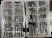
I have been asked about selling all, and if not, maybe offer matching. I would prefer selling all as a lump, but I might be persuaded to match if enough people are interested. $12/each if matched + shipping at cost.
I will make a decision in a couple of days based on feedback & interest.
I prefer PM.
R
I will make a decision in a couple of days based on feedback & interest.
I prefer PM.
R
- Home
- Amplifiers
- Solid State
- Accuphase P-7100 Amplifier Clone