Oh yes. I just stuck them in a sealed tower enclosure when I got them a few months ago. 4 on each side. No calculations. I'm very excited to see how much of an improvement the enclosure makes.
I think that this design will bring a reduction of the treble, as a push-pull
is inherently mass-loaded 😕🙄 No, maybe not !
But, yes, it will make some changement in something !
My latest idea for multiple drivers intended for just bass- because some
nasty interferences will occur as c-t-c spacing relating to the frequency and to the shape of the cone.......- is to make a triplet, each speaker placed at the extremes of an equilateral triangle 😱
I'm just finishing my 'accidental MLTL' ....3 way....😎
Pico,
I think Ryan was doing push-push not push-pull. What do you mean all push pulls are inherently mass loaded? Setting drivers as close together as possible should reduce comb interference and also only 2 on each side should minimize effect of reduced vertical dispersion of an array. Looking forward to seeing your AMLTL. Which drivers are you using?
X
So you'll need to make a drawing of your idea.
I did an isobaric push-pull 3-4 years ago, sort of FAST. I used some cheap
drivers such the Ciare HW 159. I dismantled them- well, just the internal wall- and I made a regular two way. So 2 HW 159 are sitting alone ....
In the meantime I found at the trash
 2 complete enclosures
It was a rainy day....So eventually I've got one of the most famous mid-domes
still from Ciare, and two 3-way crossovers. The tweeters, I'm using two Audax.
About the mass of air between two drivers in a push-pull...😕
I did an isobaric push-pull 3-4 years ago, sort of FAST. I used some cheap
drivers such the Ciare HW 159. I dismantled them- well, just the internal wall- and I made a regular two way. So 2 HW 159 are sitting alone ....
In the meantime I found at the trash
2 complete enclosuresIt was a rainy day....So eventually I've got one of the most famous mid-domes
still from Ciare, and two 3-way crossovers. The tweeters, I'm using two Audax.
About the mass of air between two drivers in a push-pull...😕
mass loading refers to constriction port at end to drive resonant freq lower than physical quarter wave pipe length. nothing to do with mass of air.
Ehm...what do you think the mass is composed by ?
The cone is then loaded by the mass of air in the pipe
And this mass is moved up and down -it's coupled to the cone, but
till a certain frequency because it's a mass and have a certain inertia ( and viscosity, as it's a fluid ) . So at higher frequency it's not mass-loaded and
the cone it's free to vibrate ! 😛😉
Given this assumption, the air in an isobaric ( equal-pressure ) push-pull
acts as mass loading the cone(s) because it has a certain weight.
It's also elastic, that's why I don't like isobaric no more.
Pico,
Obviously air has mass and I am not saying that the cones don't have mass loading. It is a matter of terminology in speaker design and types of alignments. The term Mass Loaded Transmission Line refers to the analogy of loading mass on the end of a vibrating cantilever tuning fork to reduce its natural quarter wave resonant frequency. The tuning fork's resonant frequency is normally a function of its stiffness or Young's modulus and length. However, adding point masses to the tips of the fork tines will reduce the natural frequency. Somebody started calling the addition of a constriction in the mouth of the quarter wave aeroacoustic resonator "mass loading" so there we are, stuck with the term. I would have called it something like "constricted vent transmission line" but I did not get to name it. 🙂
Obviously air has mass and I am not saying that the cones don't have mass loading. It is a matter of terminology in speaker design and types of alignments. The term Mass Loaded Transmission Line refers to the analogy of loading mass on the end of a vibrating cantilever tuning fork to reduce its natural quarter wave resonant frequency. The tuning fork's resonant frequency is normally a function of its stiffness or Young's modulus and length. However, adding point masses to the tips of the fork tines will reduce the natural frequency. Somebody started calling the addition of a constriction in the mouth of the quarter wave aeroacoustic resonator "mass loading" so there we are, stuck with the term. I would have called it something like "constricted vent transmission line" but I did not get to name it. 🙂
As Ryan is cutting plywood as we speak, I am for the first time cutting something other than foam core to make my next speaker: masonite board to make the baffle of a wall mount TABAQ like MLTL. It is a folded affair with overall 11.25 in wide x 17 in tall x 3.75 in deep. The csa is identical to the TABAQ at 20 square inches and length is 30.7 inches unfolded, vent is identical and will be a rectangular down firing slot. The driver will end up at one end and symmetric so that it can be used for either left or right channels. It will have foam core side walls and back panel and use Vifa driver. Since it will be wall mounted no BSC will be needed. So this is first time I needed anything besides a drill. I used jigsaw to cut the holes for the drivers.
I don't know much of the cantilever and fork tuning, luckyily you hadn't brought the aerial transmission line example with the antennas !
For what I know, my model works, as also the terminology with it.
With the TL and 1/4 wave models as example, what would change between:
closed TL or labyrinth, tapered; regular TL, straight or tapered (not considering the Voigt or expanding pipe); a TL with a duct at the terminus , which is the ML-TL. 😕🙄
Still working on the box! Almost finished. Had to stop and grab a quick bite to eat. I'll post some photos of the build in a few hours. Going to have to listen a bit before posting. haha
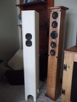
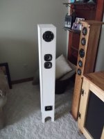
Well here it is! A quick build on a snowy day.
I've had it playing for literally 5 min and WOW! Out in the garage I had it hooked up while stuffing it. No lid no bass response. Slowly slide the lid on and poof! amazing sound.
Bad thing is now I'm going to have to build another to match. haha
Here's a before and after shot. I'll be writing up a build thread later today with more pics.
X thanks for all your help! It's greatly appreciated. Thanks again!
Attachments
😀
Sweet! How are you wiring the tweeter? Looks like a rear firing one to add spaciousness?

Very nice Ryan. You are one fast constructor.
Show us photo of bottom firing port.
Sweet! How are you wiring the tweeter? Looks like a rear firing one to add spaciousness?
Very nice Ryan. You are one fast constructor.
Show us photo of bottom firing port.
Here's a very quick write up thread that I did. Many pics. If you need more feel free to ask.
http://www.diyaudio.com/forums/full-range/234535-tangband-w3-881-mltl-build.html#post3462232
I got the tweeter out of phase right now and it firing at the wall. Going to listen to it now and flip flop it later.
http://www.diyaudio.com/forums/full-range/234535-tangband-w3-881-mltl-build.html#post3462232
I got the tweeter out of phase right now and it firing at the wall. Going to listen to it now and flip flop it later.
I have a question for folks who use MJK to model MLTL's: how do you do multi-driver setups like the above? With WinISD, having multi drivers is easy and lets the bass reflex tuning calculate both optimal box volume and vent first from which to make csa estimate based on length.
using the old rule of thumb of 1/3rd to 1/5th line length, or MJK which works between those points, i would locate the midpoint of a pair at the Dz that the MJK worksheets indicate. More than 2 drivers is likely a lot more hassle.
Yeah, but can the MJK sim directly model the effect of multi drivers ? Locating drivers based on centroid is usual practice. Effect of multi drivers on vent CSS and length is what I wax wondering if it can be done in MJK.
Hi X,
Here is the article by MJK pn how to model 2 drivers in one enclosure:
http://www.quarter-wave.com/General/Two_Drivers.pdf
With 4 drivers in bipole mode, I guess you could split the box in half and use MJK's method for 2 drivers in half the box.
Cheers, Jim
Here is the article by MJK pn how to model 2 drivers in one enclosure:
http://www.quarter-wave.com/General/Two_Drivers.pdf
With 4 drivers in bipole mode, I guess you could split the box in half and use MJK's method for 2 drivers in half the box.
Cheers, Jim
I'm looking for some help modelling a MLTL if anyone wants to help me out, thread is at http://www.diyaudio.com/forums/multi-way/234547-help-me-model-folded-mltl.html
- Home
- Loudspeakers
- Full Range
- Accidental MLTL Technique