That's the thing where it'll probably get a little unstuck - I don't want to change the curved boxes / build new ones if I can help it, these will more or less stay as they are. I'm wondering whether there would be any advantage in modifying the inside of the box to a folded ML-TL.
The top, bottom and internal volume are pretty much set now, its just a matter of modelling various internal partitions to see how it affects the output. The speaker is the HiVi B4N, I think I tuned the new box to around around 43Hz, but will have to check that out... Internal box height is around 10 1/2 inches, depth is around 9 1/2 inches, but the box curves out to an internal width of 7 inches then tapers back to 2 1/2 inches. Not entirely sure what the volume ends up at. Around 7 to 9L I believe...
Any insights as to changes to the sound? Would it be likely to affect the low-end output in a significant way? If not, I might leave them as is and design a different system using some other speakers I have lying around...
I'm curious where the rule of thumb for 3 - 4 x Sd came from for cross-sectional area. Modeling or real life? I always thought that 1 - 1.25 x Sd would be best, like traditional 'old school' transmission lines.
I'm curious where the rule of thumb for 3 - 4 x Sd came from for cross-sectional area. Modeling or real life? I always thought that 1 - 1.25 x Sd would be best, like traditional 'old school' transmission lines.
Initially from observed CSA to Sd ratios of tried and tested MLTL's using moderate Qts drivers like the Tabaq (4x5in CSA and circa 3in to 4in drivers). It turns out you need this volume to a provide enough volume for the larger Vas that these moderate Qts (0.5 to 0.7) drivers need to get sufficient bass extension with a length of about 30in for a 3in to 4in class driver and 42in for 5in to 6in class driver and 50-60in for an 8in class driver. Once I had modeling capability this rule of thumb was verified to be good. I have never used CSA in the 1.25x range as that makes a very narrow depth that barely is enough to fit the magnet and basket and is tight and prone to back reflections coloring the sound.
That's the thing where it'll probably get a little unstuck - I don't want to change the curved boxes / build new ones if I can help it, these will more or less stay as they are. I'm wondering whether there would be any advantage in modifying the inside of the box to a folded ML-TL.
The top, bottom and internal volume are pretty much set now, its just a matter of modelling various internal partitions to see how it affects the output. The speaker is the HiVi B4N, I think I tuned the new box to around around 43Hz, but will have to check that out... Internal box height is around 10 1/2 inches, depth is around 9 1/2 inches, but the box curves out to an internal width of 7 inches then tapers back to 2 1/2 inches. Not entirely sure what the volume ends up at. Around 7 to 9L I believe...
Any insights as to changes to the sound? Would it be likely to affect the low-end output in a significant way? If not, I might leave them as is and design a different system using some other speakers I have lying around...
If the box tapers down narrower at the vent it will pull the tuning frequency lower. Tapered TL's can have hard to deal with resonances in the mid range of the driver location is not modeled exactly.
Initially from observed CSA to Sd ratios of tried and tested MLTL's using moderate Qts drivers like the Tabaq (4x5in CSA and circa 3in to 4in drivers). It turns out you need this volume to a provide enough volume for the larger Vas that these moderate Qts (0.5 to 0.7) drivers need to get sufficient bass extension with a length of about 30in for a 3in to 4in class driver and 42in for 5in to 6in class driver and 50-60in for an 8in class driver. Once I had modeling capability this rule of thumb was verified to be good. I have never used CSA in the 1.25x range as that makes a very narrow depth that barely is enough to fit the magnet and basket and is tight and prone to back reflections coloring the sound.
So this larger CSA is purely for volume?
The only reason I ask, is I wanted to create a zigmahornet for the fostex ff85wk. To me the zigmahornet looks like an extremely high aspect ratio(CSA Approaching Sd), no fold MLTL (Slot port on bottom).
Also, is there any harm on having the quarter wavelength of the enclosure lower than your bass reflex port tuning? Example: enclosure 49 inches tall (70hz quarter wave) with a bass reflex port tuned to 80hz.
Sorry for the questions, and thanks for the replies!
The whole point with a mass loaded TL is so that the length is less than actual quarter wave length. The 30in Tabaq for example tunes to 55Hz.
XRK, I've been trying to make this work 'backwards' in order to determine tuning of boxes and adjust port sizes and box shapes (you may remember my 26" height constraint from the other Karlson thread). This doesn't seem to be making sense when reverse-engineering though.
For examples, I'd like to fold a Pensil 10p a la your wall mount MLTL design. But when using the volume of the traditional Pensil along with the port dimensions as a baseline in WinISD, the tuning needs to be really high to obtain the correct port length (thickness of building material). Somewhere between 65-70hz and with a big hump at 150hz and down.
Maybe this hump is a form of baffle step built into the enclosure design (approx 6db hump, which does correlate to baffle loss though at wrong frequency I think)?
Or maybe using the bass reflex port calculation as the air mass in an MLTL isn't necessarily a valid approach (ie other variables not being taken into account)?
Maybe this method doesn't work in reverse?
What do you think?
The Pensil is not a MLTL or a BR, so I am not surprised that you are having issues.
Scottmoose described it as an "air coupler" or something to that effect. Don't expect it to behave like anything else.
Scottmoose described it as an "air coupler" or something to that effect. Don't expect it to behave like anything else.
I don't know that it's not a MLTL - sure resembles one. Anyhow - just start tabula rasa and use WinISD to design a BR and then reformat to folded wall mount. The Qts of Alpairs is *perfect* for this at circa 0.5 Qts. Should work like a champ as AMLTL.
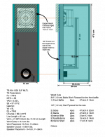
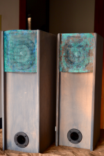
Industrial MLTL Using Accidental Technique
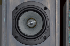
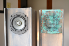
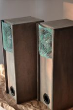
I really like these. Sound great, and the building is an ease. Used the "Accidental" method and am very pleased wit the sound. Thanks to XRK for making the design process available to a newbie like me. I realize that I may get crucified for the design choices. I'm just sick of black and silver as the only choices available in the general market. Speakers can also match the aesthetics of a room just like all of the other pieces. These are aimed at the industrial decor folks.
Finish is a washed gray chalk paint. Speaker grills are copper mesh with a vinegar/salt patina process.
Plans are complete if you like them. I always give back gratefully to this forum because of all of the help I have received.
JHutka
Attachments
I don't know that it's not a MLTL - sure resembles one.
Well, Scott designed the Pensils and explicitly stated that they aren't MLTLs. That's all I know.
If they are not MLTLs, that does explain why this method isn't working in reverse. But they aren't bass reflex either, unless the big hump and relatively high tuning is intentional.
They seem to have the TL properties taken into account as I seem to remember having read Scott write that the CS shouldn't be changed.
Is there such a thing as a "lightly" Mass Loaded TL? Simply using a smaller amount of air mass to prop up the lower frequencies. I'm having trouble wrapping my head around that if using the AMLTL technique. In BR, a lower air mass (ie shorter length) simply pushes tuning higher.
I once read an MJK explanation that described MLTL as akin to adding a weight on the end of a vibrating length, like a ruler held down over the edge of a counter-top. Add weight to the end and it vibrates at a lower frequency. So if we call the ruler without weight the TL, and the port the small weight, it would fit that a smaller air mass doesn't 'tune' like a BR port would, but does push the frequency downward (even if the mass is small-ish).
Now that begs the question about the Pensil tuning. As a TL, it's about 1,115/12 or about 100hz (12 ft being the approximate length of the corresponding quartered wave in a 36in tube). So I wonder how low the relatively small mass pushes the enclosure tuning. It must be that the smaller opening's resistance makes the driver see a much longer column of air?
Anyone know of a way to calculate this?
Last edited:
Sodacose,
Have you considered Bob Brines M10-A10 design? That design is less deep IIRC and possibly the folded dimensions more room friendly?
Dr. Jim Griffin also has a MLTL for the Alp 10.x which is on the tall and shallow side - again if height allows, a candidate for folding?
There might be a large size TABAQ variant also.
If they are not MLTLs, that does explain why this method isn't working in reverse. But they aren't bass reflex either, unless the big hump and relatively high tuning is intentional.
They seem to have the TL properties taken into account as I seem to remember having read Scott write that the CS shouldn't be changed.
Is there such a thing as a "lightly" Mass Loaded TL? Simply using a smaller amount of air mass to prop up the lower frequencies. I'm having trouble wrapping my head around that if using the AMLTL technique. In BR, a lower air mass (ie shorter length) simply pushes tuning higher.
I once read an MJK explanation that described MLTL as akin to adding a weight on the end of a vibrating length, like a ruler held down over the edge of a counter-top. Add weight to the end and it vibrates at a lower frequency. So if we call the ruler without weight the TL, and the port the small weight, it would fit that a smaller air mass doesn't 'tune' like a BR port would, but does push the frequency downward (even if the mass is small-ish).
Now that begs the question about the Pensil tuning. As a TL, it's about 1,115/12 or about 100hz (12 ft being the approximate length of the corresponding quartered wave in a 36in tube). So I wonder how low the relatively small mass pushes the enclosure tuning. It must be that the smaller opening's resistance makes the driver see a much longer column of air?
Anyone know of a way to calculate this?
The "mass loading" of MLTL is the constriction on the port. It allows a shorter than open ended TL for same tuning frequency. The only way to predict it properly is to use one of the simulator programs like HR, Akabak, MJK, AJ Horn, etc. In Akabak, you can simulate it in 9 lines of code. Really simple.
Yes, I understand that. I'm just trying to reconcile the accidental technique with the Helmholtz calculation that I guess most BR calculators to be using.
Unless this truly is just accidental. Then I'm barking up the wrong tree.
Unless this truly is just accidental. Then I'm barking up the wrong tree.
It's accidental but it will have quarter wave TL action due to length and aspect ratio. The Alpairs have Qts near 0.5 which is perfect for getting strong mass loaded output at frequency below fs of driver.
Have you tried varying the port length suggested by the BR calculations to see what effect it has?
Returning to the Pensils as an example, the port suggested by WinISD would be way more mass than the Pensil design specs (although if they are not MLTL in nature, that's moot).
But the PS220 Singularity MLTL design (approx 90lts, 4" dia x 3" port) looks ok in a WinISD BR spec as tuned to 40hz.
Returning to the Pensils as an example, the port suggested by WinISD would be way more mass than the Pensil design specs (although if they are not MLTL in nature, that's moot).
But the PS220 Singularity MLTL design (approx 90lts, 4" dia x 3" port) looks ok in a WinISD BR spec as tuned to 40hz.
I'm curious where the rule of thumb for 3 - 4 x Sd came from for cross-sectional area. Modeling or real life? I always thought that 1 - 1.25 x Sd would be best, like traditional 'old school' transmission lines.
David Weems's rule-of-thumb design [or anyone else's if there's others before him] where the closed end of a tapered pipe = 1.0-1.25x Sd is apparently based on plane wave tube [PWT] design where the tube's i.d. = the diameter of a compression driver's exit [1.0x] or the average diameter of a point source driver's complete cone area required to allow free movement [1.25x].
With the exception of Harry Olson's circa 1950 MLTL [he called it a bass reflex, missing a major marketing coup!], which is the first such alignment of this type AFAIK and properly designed based on the driver's specs using a Sd/2 vent area with a cross sectional area [CSA] = ~3.89x Sd, a design routine I initially used regardless of the driver until I learned more about these tower/column designs via crude measurements, though frankly, for a simple rule-of-thumb MLTL design routine I imagine it would fare pretty well with most of today's drivers also assuming the cab is at least 40" tall like his, which happens to be about the shortest for any useful 1/4 WL vent damping.
GM
One thing that I am still trying to figure out is what rule of thumb to use to set the length? Right now, it is one of practical considerations as you usually don't want it too long. But at the same time, you want to keep it shorter than the quarter wave length of the fb. So give a driver with a certain fs, sometimes it is possible to push its tuning to a factor of 2x below its fs. Take the TC9FD for example with an fs of 120 Hz. Because it is a high Qts driver, I can get down to 50 Hz, which is crazy. I know there is probably quite a bit of harmonic distortion here and the purists will poo poo this. But, for me, just getting to hear some nice bass around there with my wimpy 3.5 in driver is cool enough. I have heard of rule of thumbs of not pushing your tuning below 75% of the fs. If I were to follow that for the TC9FD, I would have ended up at 90 Hz - not very spectacular or impressive at all. Anyhow, I think it has a lot to do with the Qts. I think this is where a program like WinISD is handy as it will let you see how ugly the BR curve looks like when you tune below the recommended frequency. The power of the MJK simulation is that you can actually predict how flat the final response in the MLTL will look, whereas with my AMLTL method - you are just hoping. So far the hope has panned out and produced several nice sounding designs.
The first box I built messing around with Voight/MLTL type enclosure using a 2.5" dia cone out of some old radio shack powered speaker, about a 72" path length and a 3" vent the thing would produce 40hz even though some issues in the low freq response it sounded fantastic.
- Home
- Loudspeakers
- Full Range
- Accidental MLTL Technique