I get the contact mic and the usb a/d converter today. like you said earlier, there might be too big of an impedance mismatch between the piezo and the cable input.
Last edited:
Something unrelated to this thread, but found while taking measurements for this thread, is the thd on the wide open 4" midbass, on axis, taken at 12"/100db. Even though it is a superb 4" driver with a +/- 3.5mm xmax, the thd measurement below 200hz is way, way too low to be believed(The two lines should be converging at around 50hz) . Could this have something to do with the five layer cld baffle construction? What else could cause this? Anyone have any ideas?
Attachments

Last edited:
Do you have baseline measurements from when you first constructed the speaker? In other words, is it possible there is something wrong with your current measurement technique?
Your distortion at 100 Hz would be excellent performance for a 10 or 12 inch driver, so yes I agree it looks suspicious.
Your distortion at 100 Hz would be excellent performance for a 10 or 12 inch driver, so yes I agree it looks suspicious.
Maybe it is faulty. I need to look into this more thoroughly. I'll measure one of my 10" peerless xxls subs(Wide open again) using the same technique.
Do you have baseline measurements from when you first constructed the speaker? In other words, is it possible there is something wrong with your current measurement technique?
Your distortion at 100 Hz would be excellent performance for a 10 or 12 inch driver, so yes I agree it looks suspicious.
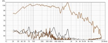
Okay, here's the wide open 10" peerless xxls sub thd taken at the exact same 12" distance at 100db/300hz, vs the 4" driver at 100db. Strange to say the least. The subwoofer measurement is exactly what you would expect. The black trace is thd and the brown trace is the noise floor. Could it be that the cld baffle construction is somehow canceling out the thd on the midbass? Doesn't make sense.
Attachments
Last edited:
Could it be that on a conventional baffle the basket vibrates, however with your laminated baffle these vibrations are much reduced? It's only when I used a driver " magnet out " that I realized how much they flex, if I rested a finger between the magnet and basket I could feel the vibration, and when I used wax to dampen that area there was an audible difference, less " zing ".
Ok I get that you guys are trying to quatisize the actual vibration of the panels to an SPL value. That is a lofty goal for a home hobbiest but worthwhile. I just think that you will always be asking is that just the panel or influence from direct output also. My point is that it is relatively easy with direct accelerometer measurements to measure panels and their frequencies and then try to reduce them as much as possible experimenting with bracing/dampening. If I can reduce them by 20-30dB then I more than likely I have taken them out of the equation. This would be more along the lines of a practical hobbiest solution.
It is a lofty goal, but we may have discovered, or re-discovered, a technique to do exactly that. Maybe... it looks promising so far, but we are still looking into it. I would say the goal is not to quantify with precision the acoustic radiation of a cabinet, but to determine if it is above or below some threshold of importance... like -20 dB for instance.
My concern with accelerometer data is that this instrument will often reveal resonances which are not sonically significant.
If we have established a baseline acoustic signature for a cabinet wall, and we want to reduce the acoustic radiation at xyz Hz by 12 dB, then yes, accelerometers can help with that. But by themselves they can not establish the baseline.
What if the resonances you are measuring are already inaudible? Reducing a resonance in a finished cabinet by 20 dB can be a Herculean task. What if it is not even necessary?
My concern with accelerometer data is that this instrument will often reveal resonances which are not sonically significant.
If we have established a baseline acoustic signature for a cabinet wall, and we want to reduce the acoustic radiation at xyz Hz by 12 dB, then yes, accelerometers can help with that. But by themselves they can not establish the baseline.
My point is that it is relatively easy with direct accelerometer measurements to measure panels and their frequencies and then try to reduce them as much as possible experimenting with bracing/dampening. If I can reduce them by 20-30dB then I more than likely I have taken them out of the equation.
What if the resonances you are measuring are already inaudible? Reducing a resonance in a finished cabinet by 20 dB can be a Herculean task. What if it is not even necessary?
Why not? I calibrated my contact mic to the same level as my measurement mic.But by themselves they can not establish the baseline.
I tested the feasibility of my idea in post #118: using a sacrificial driver to induce structural vibration into the cabinet without creating a significant sonic radiation. The sacrificial driver would have the diaphragm removed so there would be very little sound produced. An equivalent mass would be added to the dust cap to simulate the mass properties of the removed cone. In theory, if the
The potential of this approach is that the sonic radiation of the intact driver is known and fully understood. The intact driver can be replaced with the sacrificial de-coned driver. The de-coned driver produces little sound, but it does produce fully representative cabinet vibrations. Now the cabinet signature can be easily measured without being masked by driver radiation.
I had two goals for this feasibility test: (1) Determine if a driver be de-coned and then have the mass restored in a way which preserves the original inertia load on the motor and chassis. (2) Determine how much acoustic radiation is produced by the de-coned driver.
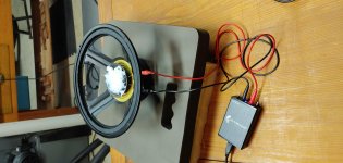
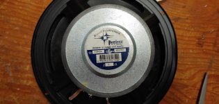
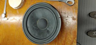
I selected a Peerless 10-inch driver (831759, 4 ohm) which was my younger brother’s automobile subwoofer 20 years ago. The spec sheet lists the sensitivity of this driver as 91.5 dB @ 2.83V 1 meter. When I measured the driver with no baffle, I had significant front-back cancellation at low frequencies, but between 800 Hz and 1500 Hz I measured approximately 90 dB at 1 meter 2.83 V. I cut the cone and rubber surround out of the driver, down to the dust cap. The mass of the cone/surround that I removed was 29 grams. The spec sheet for the driver lists the Moving Mass (including air load) of the drive as 52 grams. I decided to start with an added mass of 29 grams. I used silicone caulk because it loses little mass as it cures.
The potential of this approach is that the sonic radiation of the intact driver is known and fully understood. The intact driver can be replaced with the sacrificial de-coned driver. The de-coned driver produces little sound, but it does produce fully representative cabinet vibrations. Now the cabinet signature can be easily measured without being masked by driver radiation.
I had two goals for this feasibility test: (1) Determine if a driver be de-coned and then have the mass restored in a way which preserves the original inertia load on the motor and chassis. (2) Determine how much acoustic radiation is produced by the de-coned driver.
I selected a Peerless 10-inch driver (831759, 4 ohm) which was my younger brother’s automobile subwoofer 20 years ago. The spec sheet lists the sensitivity of this driver as 91.5 dB @ 2.83V 1 meter. When I measured the driver with no baffle, I had significant front-back cancellation at low frequencies, but between 800 Hz and 1500 Hz I measured approximately 90 dB at 1 meter 2.83 V. I cut the cone and rubber surround out of the driver, down to the dust cap. The mass of the cone/surround that I removed was 29 grams. The spec sheet for the driver lists the Moving Mass (including air load) of the drive as 52 grams. I decided to start with an added mass of 29 grams. I used silicone caulk because it loses little mass as it cures.
Attachments

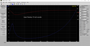
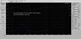
I show the impedance curves for the intact driver and also after it has been de-coned and modified with 29 grams of silicone. The original driver had an Fs = 28 Hz and Qts = 0.38. The modified de-coned driver has an Fs = 38 Hz and Qts = 0.3 . However, there is a lot of noise in the impedance curve. Obviously, the rubber surround was providing a lot of damping and control over the cone, and with only the spider controlling the voice coil, there is now a lot of uncontrolled motion.
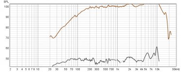
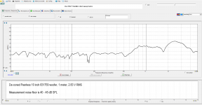
Next, I made frequency response curve of the driver at 1 meter, 2.83 V RMS. As can be seen, there is no measurable sonic output below 500 Hz (it was below my noise floor of 40 – 45 dB SPL). Above 500 Hz the signal rises to about 63 dB SPL at 800 Hz and stays above 60 dB until 1.5 kHz.
The baseline driver output would be about 90 dB SPL, so this sacrificial de-coned driver is more than 25 dB below that at 800 Hz, and more than 45 dB below baseline in the region below 500 Hz.
If more mass were added to get the Fs down to the original baseline of 28 Hz, the overall output of the de-coned driver would drop even more.
Based on this demonstration, I believe it is feasible to use a de-coned driver to induce representative driver vibration loads into a cabinet. The resulting cabinet acoustic signature can be directly compared to the baseline driver radiation. Cabinet signature above -25 dB (relative to baseline) would have been detectable in this demonstration. Signatures below -25 dB would not have been reliably detected.
Attachments
The potential of this approach is that the sonic radiation of the intact driver is known and fully understood. The intact driver can be replaced with the sacrificial de-coned driver. The de-coned driver produces little sound, but it does produce fully representative cabinet vibrations. Now the cabinet signature can be easily measured without being masked by driver radiation.
If you place your driver in a cabinet then sound radiation from the inside of the cabinet will largely cancel sound radiation from the outside in the same manner as the suspension of your cut-down driver. (I will set aside discussion of what is going on in the near field of your cut down driver). You will have to block off the opening but in a way that does not interfere with the cabinet motion or radiation. Simply bolting a circular blanking plate will both stiffen the cabinet and radiate significant sound. Pushing a separately supported cylinder with a soft sealing gasket against the frame/baffle covering the hole might work if you can prevent the cylinder's surface from radiating significant sound, interfering significantly with the cabinet radiation and to dissipate the sound within the cylinder.
It is also important to recognise that only one of the two mechanisms of driving the cabinet is present. At low frequencies for largish drivers the internal pressure within the cabinet will be putting more work into the cabinet motion than the reaction force on the drivers. Values here for a small sealed subwoofer cabinet (I really should finish the work and present it!). Nonetheless you are including the most important mechanism because the loud intrusive resonances will occur at relatively high frequencies.
Andy beat me to it. This is a clever approach and can yield some interesting info, but does not include box panel vibration caused by sound only. And that energy can be significant. Think of a helicopter passing overhead, a thunder clap, a sonic boom. All coupled by air only, yet they can make your house whole shake.
What this can certainly tell us is how much vibration comes thru the driver frame into the box panels. Happy New Year and new sonic investigations!
What this can certainly tell us is how much vibration comes thru the driver frame into the box panels.
Happy New Year and new sonic investigations!Well ... this is why I am enthusiastic about the Remlab approach. I did this little demonstration to close out the original idea I had. I think it could be made to work, but it would need further development. Containing cabinet radiation from the interior of the box is the biggest challenge. At some frequencies there could be a null, and at others there could be a +3 dB addition of non-correlated sound... Some kind of absorbent plug or hat would be needed.
But in the end I do not think this method will be as revealing as the Remlab approach. In addition, it is more complicated than the Remlab approach, and it requires a sacrificial driver. Maybe that is OK with a $40 driver, but I don't see very many people willing to destroy a $250 driver to do this test...
j.
Why not? I calibrated my contact mic to the same level as my measurement mic.
Hi Pano - I went back and re-read your posts and re-looked at your data. If the ultimate goal is to determine the in-room response of the cabinet, it seems to me that your contact mic is definitely a step closer to this goal than an accelerometer. But as you pointed out in an earlier post, the surface area of a panel being measured will play a role.
It seems to me that if your contact mic measured 90 dB on a 5" x 5" panel, and then later measured 90 dB on a 12" x 12" panel, the second case would contribute a significantly greater acoustic energy into the room... Or am I confused about how this works?
As you guys are pointing out how is it "representative"of the sidewall behavior under normal operation when the test conditions completely remove the pressurization effect of the intact speaker on those sidewalls. Are you saying that all sidewall resonances occur from mechanical motor movement of the driver?
Are you saying that all sidewall resonances occur from mechanical motor movement of the driver?
Yes, that is the theory, and it is backed up by evidence... but I can't remember who or when that was established. Maybe someone else will have a link (??) The exception, apparently, is subwoofers. However, it is quite easy to build a cabinet where the first mode resonance is above the subwoofer operating range. It is those pesky 200 - 600 Hz resonances that seem to be most intrusive.
You are not confused, that is how it works. 😉Or am I confused about how this works?
But a speaker box panel is not a speaker cone, so a 1:1 correlation between the SD of the two likely isn't valid. The box panel isn't a piston over its entire surface, the way a speaker cone is because the panel corners don't move as much as the center. Of course a larger panel that reads the same vibration as a small one would be louder, as per your example. Twice the surface area with the same displacement means +6dB in SPL IIRC.
The best I can think of to compare cone output to box panel output is to take 5 or more readings from different points on the panel and add them together. Doing so should give you a good idea of how much sound is coming off the panel vs the cone. Obviously a rather time consuming practice.
- Home
- Loudspeakers
- Multi-Way
- Accelerometers to measure panel vibrations?