A better pickup is going to make a for better results.
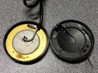
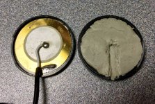
The cheap-o contact mics I use are just a piezo disk in a light plastic box. Adding heavy damping putty to the inside of the back shell reduced air borne pick up by an easy 12-14dB. But only under 2000 Hz, above that it had no effect. Still worthwhile, for sure.
The cheap-o contact mics I use are just a piezo disk in a light plastic box. Adding heavy damping putty to the inside of the back shell reduced air borne pick up by an easy 12-14dB. But only under 2000 Hz, above that it had no effect. Still worthwhile, for sure.
Attachments
Do you mean this one?Go to SparkFun website pick up $10 3axis accelerometer with buffered voltage outputs.
SparkFun Triple Axis Accelerometer Breakout - ADXL337 - SEN-12786 - SparkFun Electronics
Looks easy to use, but bandwidth is a bit limited. Do you know if it's sensitive to outside noise?
So trying to understand where this thread is really going. It started with Headunit asking about accelerometers to measure vibration in enclosures. That makes sense to me. Identify vibrations and experiment with bracing/dampening and remeasure. Are you guys trying to measure side panel vibrations acoustically with a mic and therefore need to dampen direct speaker output. Why not just use an accelerometer to start with.
The thread has moved to a new set of questions to be answered: What is the sound radiating from a speaker cabinet? How much, and at what frequency? At what point does it become audible with program material?
Measuring vibration (acceleration) is interesting, and it can tell us something, but in a cabinet with significant bracing or damping or both, it is difficult to translate that cabinet wall acceleration into SPL.
There are a lot of ways of inducing cabinet vibrations to discover the natural modes. And I am certain that any real structure can be made to vibrate at its natural frequencies...
But what we want to know is this: when a speaker is playing at 95 dB SPL, what is the level of cabinet sound: if it is -6 dB, I believe it will be audible and we will need to take some corrective action... if it is -25 dB then I believe it will be inaudible and we can safely ignore it. If it is somewhere in between it will depend on the frequency, and in my opinion we will need to evaluate it with music (not simply test signals). I think each DIY designer will need to decide how much cabinet signature they can tolerate.
Measuring vibration acceleration will not answer the question. Inducing vibration loads into the cabinet with something other than the actual driver will not answer the question. Using the actual driver to excite the cabinet and then measuring the cabinet SPL signature without the driver radiation will answer the question.
And that is where this thread is going...
J.
Last edited:
I do not think it is that simple. It’s not only levels on steady state signals but distortion and time effects also play their role. And the simulation with a force not producing acoustic output actually could work pretty well. IMHO all experiments with two speakers facing each other neglect the baffle output which often is problematic. So...… what we want to know is this: when a speaker is playing at 95 dB SPL, what is the level of cabinet sound: if it is -6 dB, I believe it will be audible and we will need to take some corrective action... if it is -25 dB then I believe it will be inaudible and we can safely ignore it. If it is somewhere in between it will depend on the frequency, and in my opinion we will need to evaluate it with music (not simply test signals). I think each DIY designer will need to decide how much cabinet signature they can tolerate.
Measuring vibration acceleration will not answer the question. Inducing vibration loads into the cabinet with something other than the actual driver will not answer the question. Using the actual driver to excite the cabinet and then measuring the cabinet SPL signature without the driver radiation will answer the question.
Turns out not to be so easy, right? 😀
And those are just some major issues, not to mention the details.
- If we measure with contact mics or accelerometers, how do we know the amount of sound radiated into the listening space compared to the cone?
- If we do a face to face cancellation, how do we insure the best cancellation and be sure that we are measuring the box and not the driver?
- What about the baffle?
And those are just some major issues, not to mention the details.
I do not think it is that simple. It’s not only levels on steady state signals but distortion and time effects also play their role. And the simulation with a force not producing acoustic output actually could work pretty well. IMHO all experiments with two speakers facing each other neglect the baffle output which often is problematic. So...
It was very late when I wrote that, and yes I was overly-simplifying things a bit.
Toole and Olive have presented evidence that cabinet resonances are only audible when they affect the frequency response of the system in a measurable way. They theorized that when we hear a panel resonance, we are hearing the frequency response aberration, not the delayed energy or time smearing. Now I am not quite willing to accept that we will NEVER hear the time-delay, or ringing, of a bad cabinet, but I do believe that the ringing has to be pretty awful for us to hear it (based on Toole & Olive work).
I regret I did not do a harmonic distortion measurement when I performed my quick-and-dirty experiment. If I repeat it, I will do so, along with using a thick layer of foam between the two speakers similar to the felt that Remlab used. I do believe that distortion products from the cabinet might be audible. I will also do near-field measurements of the panels because, as Andy19191 pointed out, we may be measuring things in the far field which are not emanating from the cabinet wall, such as cavity resonances.
The issue with cabinet radiation from the front baffle is a tough nut to crack. I can not think of a way to measure it using the Remlab face-to-face null technique. It is possible that the best way to quantify it might be to use what I described in Post 118, a driver with no diaphragm. I have an old cheap 10 inch driver, and I might try removing the cone and seeing how much sound comes off of the dust cap and spider. If it is too high it will negate this technique which, of course, depends on being able to induce structural vibrations without producing acoustical output.
On a positive note, any front baffle radiation is fully captured in the on-axis FR measurements, CSD plots, and harmonic distortion measurements. So if we are not seeing anything alarming in the on-axis measurements, there is probably nothing going on.
With the kind of speakers I build, I am not concerned about front baffle radiation. My speakers use narrow baffles which are highly braced, reinforced, and very thick (1.5” to 2” thick). All of this leads to a very high stiffness, low deflection structure. So for me, the Remlab face-to-face technique may be appropriate. It may be less appropriate for wide baffles, or lightly constructed baffles. I am hoping that Pano’s contact mic experiments reveal those aspects which we can not see with the Remlab technique.
J.
I can easily do two contact mic measurements of the front baffle. One with the mic in contact with the baffle, and a control measurement with the mic in the air or perhaps attached to something solid like a brick.
What will remain difficult to determine is how much of that panel vibration makes it to our ears.
What will remain difficult to determine is how much of that panel vibration makes it to our ears.
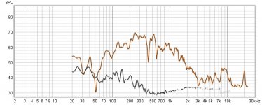
Kind of strange measuring the thd of a distortion source, but here it is..
These are thd measurements of..
Side panel, central axis at 12", with felt inserts.
Wide open midbass driver, central axis, at 12"
Actual spl, not that it's relevant.
These are thd measurements of..
Side panel, central axis at 12", with felt inserts.
Wide open midbass driver, central axis, at 12"
Actual spl, not that it's relevant.
Attachments
My original idea was to simply allow anyone, without measuring equipment or money, to hear what their speaker panels are putting out into the room while using a correlated/mono pink noise source. It can't be stated strongly enough that that is the true value of doing this test!
The actual measurements using sweeps are simply an "attempt" to accurately record what we are hearing with at least some modicum of accuracy. Ultimately, the debate about the audibility of these resonances while listening on axis, is very similar to the the debate about the audibility of driver thd. Some think the case is closed, and some do not.
The actual measurements using sweeps are simply an "attempt" to accurately record what we are hearing with at least some modicum of accuracy. Ultimately, the debate about the audibility of these resonances while listening on axis, is very similar to the the debate about the audibility of driver thd. Some think the case is closed, and some do not.
Last edited:
Your work is related to structural vibration testing spectrum analysis, using Fast Fourier Transform analysis. Impact testing of structures and foundations is also performed.
An overview:
Basics of Structural Vibration Testing and Analysis — Crystal Instruments - Leading Innovation in Vibration Testing, Condition Monitoring, and Data Acquisition
I deal with the related field of rotating equipment, pumps, fans, centrifuges, etc. Accelerometer readings can be used to calculated displacement, velocity, and acceleration. Equipment vibration readings are typically given as 1) an overall velocity reading (in./sec) and 2) shown as a spectrum analysis chart of vibration velocity at the over the frequency range. Velocity readings are generally used between 10 Hz to 1000 or 2000 Hz as a best indicator of "severity". There are plenty of exceptions, as large turbines (shaft weight in the tons) may use proximity probes which measure displacement.
Last edited:
It's not that I have a problem with accelerometer measurements, it's just that in audio, everything is ultimately about "audibility" of resonances, not necessarily about the resonances themselves. John Atkinson has been doing cabinet accelerometer resonance measurements for close to 30 years now, and even though I have studied them with great interest, I always wondered how they translated into what is actually getting out into the room.
The Dunlavy sc-1 accelerometer measurements performed by JA, and posted in this thread, corroborate amazingly well with my own acoustic measurements(Also posted in this thread), so in a way, his accelerometer measurement are validifying my measurements, and my measurements are validifying the audibility of his accelerometer measurements while using the same speaker. I don't think that an audibility check has ever been done before on an actual accelerometer measurement of a loudspeaker panel until now. Please correct me if I'm wrong🙂
The Dunlavy sc-1 accelerometer measurements performed by JA, and posted in this thread, corroborate amazingly well with my own acoustic measurements(Also posted in this thread), so in a way, his accelerometer measurement are validifying my measurements, and my measurements are validifying the audibility of his accelerometer measurements while using the same speaker. I don't think that an audibility check has ever been done before on an actual accelerometer measurement of a loudspeaker panel until now. Please correct me if I'm wrong🙂
Last edited:
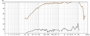
The accelerometer measurement is at the bottom of the page..
Dunlavy Audio Labs SC-I loudspeaker Measurements | Stereophile.com
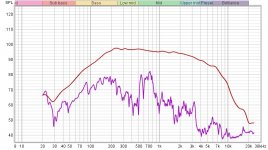
This is my own acoustic measurement of the sc-1 side panel(Using the null technique) taken at 12"(Ignore 10cm label) vs the front of the speaker at the same measuring distance. No tweeter connected. The peak at 730hz is only 13db below the fundamental. That's pretty loud. At 150hz and below, the panel is almost acting like a passive radiator.
Dunlavy Audio Labs SC-I loudspeaker Measurements | Stereophile.com
This is my own acoustic measurement of the sc-1 side panel(Using the null technique) taken at 12"(Ignore 10cm label) vs the front of the speaker at the same measuring distance. No tweeter connected. The peak at 730hz is only 13db below the fundamental. That's pretty loud. At 150hz and below, the panel is almost acting like a passive radiator.
Attachments
Last edited:
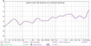
OK, as far as I can determine, this is the air borne pick up of my putty filled contact mic vs vibration pickup. Actually vibration + air.
It runs from about -40dB to -23dB @ 1kHz to -15dB @t 8kHz. That's how far below vibration pickup the thru the air pickup is. That is with the contact mic stuck to a concrete block sitting on a concrete floor for the thru air test.
Not perfect, but it doesn't skew the measurement too much.
It runs from about -40dB to -23dB @ 1kHz to -15dB @t 8kHz. That's how far below vibration pickup the thru the air pickup is. That is with the contact mic stuck to a concrete block sitting on a concrete floor for the thru air test.
Not perfect, but it doesn't skew the measurement too much.
Attachments
Remlab ... is that 730hz peak a product of the 45hz blip? It would also be interesting to determine how much of the panel vibration contributes to the on axis LF response profile. ... or perhaps, damp the cabinet exterior during that measurement.
Maybe what's needed is a blimp* for the speaker box. Make one from sand and lead shot to drape around the speaker and stop box noise from getting into the air. Measure with out without the blimp to see what's coming from the box.
*Like a camera blimp, the soundproof casing for movie cameras, not the thing that flies.
Sound blimp - Wikipedia
Standard rigging sandbags could work or serve as a model. Lighting Sandbags - 300 Different Sandbags to Choose From
*Like a camera blimp, the soundproof casing for movie cameras, not the thing that flies.
Sound blimp - Wikipedia
Standard rigging sandbags could work or serve as a model. Lighting Sandbags - 300 Different Sandbags to Choose From
I would say that because the baffle is parallel with the surface of the driver(sympathetic resonances) and facing the listener, it is profoundly more important than side panel resonances(Perpendicular to the driver and listener, and not as sympathetic). That's why I spent a large amount of money, time and thought developing the baffles that I did. The issue is so important to me, that nothing was left to chance. A five layer sandwich of alternating layers of aluminum and sorbothane(six layers, if you count the sorbothane gaskets between the cabinet and the baffle). It was also chamfered behind the midbass, which helps eliminate another potential cause of distortion. The baffle is also completely decoupled(with sorbothane) from the cabinet itself.I do not think it is that simple. It’s not only levels on steady state signals but distortion and time effects also play their role. And the simulation with a force not producing acoustic output actually could work pretty well. IMHO all experiments with two speakers facing each other neglect the baffle output which often is problematic. So...
Another subject that is not really focused on, is how baffle vibrations can reflect back to the midbass driver that created them, and how midbass vibrations through the baffle can profoundly effect the tweeter output. Think about this, if a midbass can vibrate an object as heavy as a cabinet, what is it doing to a transducer, inches away, who's diaphragm weighs only a couple grams at the most? That's why I also mechanically isolated the tweeter completely from the midbass. It is sitting on the second layer of aluminum(The midbass is on the top layer), with it's own sorbothane layer between it and it's mounting plate.
I'm not expecting anyone to follow this route. All I'm saying is that the baffle really is that important compared to the side panels, and if you kill the vibration in the baffle before it reaches the side panels, the tweeters, or even back to the midbass itself, it makes the side panels that much less relevant.
Last edited:
The fact that Dunlavy used absolutely no bracing in this cabinet could very easily mean that all the side panel vibrations are related to a certain degree. As far as the low frequencies are concerned, this speaker rolls off pretty quickly below 200hz, so bass output is minimal anyway, even with the passive, or should I say "sympathetic" radiators.Remlab ... is that 730hz peak a product of the 45hz blip? It would also be interesting to determine how much of the panel vibration contributes to the on axis LF response profile. ... or perhaps, damp the cabinet exterior during that measurement.
Hey, I spent $1,200 on these back in '94, so I'm not very happy about this! I am happy about being able to do the direct comparison though🙂
Last edited:
Looking at measurement data is very interesting, but the experiment anyone can do, even without a measurement system is the out of phase correlated pink noise test.
1. Place the speakers facing each other as close together as possible.
2. Wire one out of phase with the other.
3. Cover one's side panels with thick blankets(The more, the better). This is to help keep one cabinet's out of phase resonances from canceling out the one you're listening to.
4. Play "correlated"(mono) pink noise. This is critical. I actually stream a 1/2 hour track from amazon music. Other streaming sites should have it or something similar. Any source is fine as long as it specifically says "mono" or "correlated".
5. Listen. Cabinet noise, for the most part(Below 1khz), should swamp any driver noise that's left.
While using this technique on well matched drivers(super easy with a dsp crossover that can be adjusted with .1 db increments)and doing sweeps instead of pink noise, could a contact mic or accelerometer pick up enough useful info about baffle resonances to make it useful? Should I try this?
- Home
- Loudspeakers
- Multi-Way
- Accelerometers to measure panel vibrations?