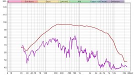
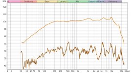
So here are the Dunlavy's and my diy's, side by side in an identical, mic'd panel measurement comparison. Dunlavy's first with all drivers being run wide open. Everything above 1khz is pretty irrelevant in this discussion
Attachments
Last edited:
Thanks. I'm feeling a bit dense and I apologize. The chart on the left is the Dunlavy, on the right your DIY. In each of those, the top smooth line is one driver direct? Or two drivers in opposite phase? And then the bottom plot is the mic very close to the cabinet wall? With drivers in opposite polarity?
Sorry for not getting the details.
Sorry for not getting the details.
No problem. It's me, not you🙂. The top line is the direct, on axis output of the speaker operating by itself. The bottom measurement is of the side panel of that one speaker, while that speaker is firing directly into the other speaker with out of phase, correlated pink noise. The other speaker is also covered up with a ton of thick blankets to minimize any cancelation that may occur from the out of phase panels. Hopefully that makes sense🙂
Oh yes, and the mic is exactly 12" away for each and every measurement(that's including the panels, so real comparisons can be made), and all appliances, including the refrigerator and the furnace are turned off. my speaker is also about 3 or 4db louder during the test too. I should have matched them a little better
Oh yes, and the mic is exactly 12" away for each and every measurement(that's including the panels, so real comparisons can be made), and all appliances, including the refrigerator and the furnace are turned off. my speaker is also about 3 or 4db louder during the test too. I should have matched them a little better
Last edited:
Great, thanks! That clears up the mystery and it's also a very good procedure.
Tomorrow I will try this on some funk little MDF boxes I made a couple years ago. To the mic measurements I can add contact mic measurements which should make for an interesting comparison.
Tomorrow I will try this on some funk little MDF boxes I made a couple years ago. To the mic measurements I can add contact mic measurements which should make for an interesting comparison.
I made a mistake in the description of how I did it. It was not correlated pink noise on any of the measurements, it was all done using a quick sweep on each. Sorry.
The out of phase, correlated pink noise is good for actually listening with your own ears at what the box panels are putting out, sustained over time.
Once again, sorry for any confusion this caused.
The out of phase, correlated pink noise is good for actually listening with your own ears at what the box panels are putting out, sustained over time.
Once again, sorry for any confusion this caused.
Last edited:
The contact mic will definitely give added info that I could have used myself. Should be interesting
I'm thinking of getting this. It's a 1/4" jack to usb With a 48khz a/d converter built in. It can be hooked up directly to a contact mic, and plugged straight into the computer and be used with rew, I'm hoping.
https://www.amazon.com/USB-Guitar-C...aed85&pd_rd_wg=RNfw9&pd_rd_i=B07STTRGFW&psc=1
https://www.amazon.com/USB-Guitar-C...aed85&pd_rd_wg=RNfw9&pd_rd_i=B07STTRGFW&psc=1
Last edited:
Yeah that should work. It doesn't say what the input impedance is, but as it's for guitar, we can hope for 1 meg. Will you measurement software send the sine sweep out of a different sound card then this cable as the input? Some will, some won't,
https://www.diyaudio.com/forums/att...asure-panel-vibrations-dunlavy-panel-10cm-jpg
This says 10cm, but in this measurement, it was actually 12". I replaced the old 10cm file with this, while forgetting to change the heading. Once again my apologies for any confusion this may have caused.
This says 10cm, but in this measurement, it was actually 12". I replaced the old 10cm file with this, while forgetting to change the heading. Once again my apologies for any confusion this may have caused.
Art Ludwig used a guitar pickup to measure vibration. Not sure how effective that is vs some of the other suggestions here.
Loudspeaker construction (search for "pickup")
Loudspeaker construction (search for "pickup")
I have some, they work. The also will pickup some airborne sound, but at a lower level. Low enough to be useful.
First look
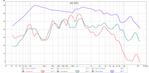
OK, I decided to play along and here is a first look. These are small homemade boxes of 12mm MDF. No bracing and the drivers are some cheap 6" fullrange with whizzer. I don't get a good null putting them face to face, but it's all I have for this test.
On the graph Blue is one driver only with the mic about 13mm from the cone surface. Red is a piezo contact mic on the side of the box. Green is a measurement mic about 4mm above the contact pickup mic. For these two measurements the box was face to face with the other speaker in reverse polarity, giving some airborne cancellation.
I do not know the sensitivity nor the frequency response of the contact mic. It is just shown as relative to the measurement mic at the same position. It does show some resonant peaks that are not shown by the normal mic.
Attachments
Fascinating. I hope I can get mine to work through the usb. Used all together, it definitely makes a more interesting data set. What happens above 1.5khz is pretty irrelevant, but below that point is very interesting, and they track quite well. Closer than I thought they would.
Tomorrow I'm going to stick the contact mic onto the driver cone to get an idea of its FR and levels. Compare it to a measurement mic at the same spot. It might tell me something.
Hopefully it wont make the cone too lopsided. That will be an interesting measurement nonetheless
Yeah, the contact mic weighs 4.5g and the cone about 8-9 grams so it will definitely make a difference. I figure if measured thru the air with the contact mic on the cone, that will at least give some reference. More than I have now, which is nothing.
This is a fairly effective and inexpensive way to see what the panel is putting out vs on axis. .
That is an understatement. This method looks to be both very revealing and very easy... it beats the snot out of my idea of cutting the cone out of a sacrificial driver.
Remlab, the performance of your cabinet wall is outstanding. Even with no resonance at all, 3/4" plywood and MDF will have about 15 to 25 dB of sound attenuation: about 15 dB below 250 Hz, about 20 dB at 1 kHz, and about 25 dB at 5 kHz. You are getting quite a bit more attenuation. This is evidence of (1) very good accoustical damping within the box, and (2) little or no structural resonance. Nice.
Jim
I Thank you, hifijim!
I have to admit, I was very unnerved about doing the measurement on my boxes that I spent so much time on and believing in. "Theory" vs what actually happens in practice can sometimes be very disappointing🙂
I have to admit, I was very unnerved about doing the measurement on my boxes that I spent so much time on and believing in. "Theory" vs what actually happens in practice can sometimes be very disappointing🙂
Looking at measurement data is very interesting, but the experiment anyone can do, even without a measurement system is the out of phase correlated pink noise test.
1. Place the speakers facing each other as close together as possible.
2. Wire one out of phase with the other.
3. Cover one's side panels with thick blankets(The more, the better). This is to help keep one cabinet's out of phase resonances from canceling out the one you're listening to.
4. Play "correlated"(mono) pink noise. This is critical. I actually stream a 1/2 hour track from amazon music. Other streaming sites should have it or something similar. Any source is fine as long as it specifically says "mono" or "correlated".
5. Listen. Cabinet noise, for the most part(Below 1khz), should swamp any driver noise that's left.
Last edited:
- Home
- Loudspeakers
- Multi-Way
- Accelerometers to measure panel vibrations?