Thanks John. The main contention here seems to be "How audible are the box vibrations?" At least compared to the radiation of the drivers. That may not be easy to tease out of the measurements.
Not salt. You mean lycopodium powder. Everybody knows that (OK, every audio experimenter knew that when I was a kid). Of course surface has to be horizontal or close to it. And be sure to use your synch strobe (ahem, ahem).....Maybe a simpler way would be sprinkle salt on the panel and see what happens...
(Just google "lycopodium powder (a highly flammable substance composed of clubmoss spores) sits on top of a vibrating stereo speaker".)
B.
My comment was just a thought. May not be practical. As noted the problem is that the acoustic output from cabinet surfaces is generally well below the driver's output. Right there, if that's the truth, it's not a big issue. But if it were significant, using a 2 channel measurement system you could attach the accelerometer to the driver and then use it's signal as a calibration signal for the SPL. The SPL measurement has to be anechoic. But given that both mic and accelerometer would be pretty flat at low frequency the result should be a flat curve at low frequency. Any sharp discrepancies in amplitude would be an indication of cabinet resonances, or so I would hope. Well, you would still have the baffle step in there too.
But if you really want to isolate panel resonances the way to do it would be with a laser scan of each surface. You could generate a plot of x-y position on the surface with amplitude that evolved as a function of frequency, f(t). Capture it on video and then play it back to watch the resonances evolve (in time) as the frequency changes. Like looking at the surface of a lake as the ripples change.
Maybe a simpler way would be sprinkle salt on the panel and see what happens. As soon as I though of that I figured someone on YouTube would have done it. Sure enough, here is a video showing doing that. Amazing Resonance Experiment! - YouTube
Doesn't give amplitude info but shows panel modes.
Amplitude info, no, but if you build a box to have as little resonance as possible, using the salt test with a very slow sweep at different amplitudes on the finished speaker should give you a lot of information you couldn't get otherwise. Great idea.
Granite loudspeaker. Interesting accelerometer data but the manufacturer sure did drop the ball on everything else. Painful.
Acora SRB loudspeaker Measurements | Stereophile.com
Acora SRB loudspeaker Measurements | Stereophile.com
Last edited:
Seems like the ability to take any vibration data and marry it to an equivalent SPL that said panel would produce is an issue. If one was concerned with just that aspect, would one way to do that be to face the driver up to the back side of an "infinite" baffle with a hole in it to eliminate the drivers output interference and measure the SPL of the enclosure minus the drivers forward contribution.
A cinder block building with a hole in the wall would be suitable. Enclosure measurements could be made inside the building with the driver firing toward the outdoors.
A cinder block building with a hole in the wall would be suitable. Enclosure measurements could be made inside the building with the driver firing toward the outdoors.
Yes, and I believe this has been done. One thing not accounted for is the box noise coming out of the driver. But it does seem a good way to measure the rest.
So we have right in our forum "A Study of DML's as a Full Range Speaker", so why not use a DML to excite your box panels in a consistent way? I'd guess by playing a .mp3 recording of an impulse transient, this would be more consistent than a knuckle rap test.
I remember an EMC engineer describing EMI suppression solutions as having the quality of what he called "the Sausage Effect". Squeeze down here, the energy pops up over there. This quality should give a hint as to the solution, right?
I see square and rectangular cabinet walls as a membrane-o-phone. It's like a drumhead. Moons ago, I observed a drumhead's motion using a strobelight. You could clearly see different parts of the head's motion at different frequencies, when the strobe was tuned close to the frequency of the motion.
I think that observation maps quite nicely to the "pin it here" and the energy simply moves over there, albeit at a higher frequency and fortunately less amplitude. So I think the idea of a damped (energy absorbing) brace is a thought in the right direction. Pin it with something that doesnt conduct as well and absorbs.
Surprising to see no mention yet of Daves holey tic tac toe swiss cheeze internal bracing style, taking a substantial part of the cabinets internal volume for just "brace". I wonder what would happen if you did that with 3/4 rubber stall mat, for $50 for 4' X 8' sheet @ many farm supply stores. That would be one heavy speaker enclosure! I'd only assume that material would absorb energy, dampen by mass and not conduct like a wood stick or plate would.
The cheapest and easiest way would be to place two loudspeakers face to face, as close together as possible and wire them out of phase. As long as they are closely matched, the only audible output should be from the enclosures themselves. Placing an absorptive panel between and to the side(perpendicularly to the panels) would keep each box side panel resonance from canceling the other out enough to take nearfield measurements
Last edited:
Building out of thin material like 1/8" foamcore or plywood will show you that quick. Brace it here, it now vibrates over there, but at a higher frequency. 🙂I think that observation maps quite nicely to the "pin it here" and the energy simply moves over there, albeit at a higher frequency and fortunately less amplitude.
The cheapest and easiest way would be to place two loudspeakers face to face, as close together as possible and wire them out of phase. As long as they are closely matched, the only audible output should be from the enclosures themselves. Placing an absorptive panel between and to the side(perpendicularly to the panels) would keep each box side panel resonance from canceling the other out enough to take nearfield measurements
Actually, you could simply cover one of the speakers with a thick blanket(Or several for that matter), which would reduce the box resonance audibility on the adjacent speaker to totally negligible levels. That way you could get an 'almost' pure measurement from one box panel at a time.
Last edited:
You could do it the hard way. Build one box normally and another with sand filled double walls. Sand filled walls do a LOT to kill vibrations. Measure the difference between the two.
Or just make a normal one and bury it in sand. 😀
Or just make a normal one and bury it in sand. 😀
I remember this from back in '94 when I actually owned these loudspeakers(Dunlavy SC-1's) John Atkinson did something with them during the review that I never forgot. I don't recall him doing it since, at least as a way to hear the cabinet.
"Although the drive-units receive some break-in at the factory, DAL suggests it takes about 12–15 hours for the woofers to reach their specified 80Hz bass-tuning frequency. Accordingly, I ran them in on the pink noise and swept-tone track from the XLO/Sheffield Lab Test CD at 6V RMS for 12 hours before I did any serious listening (footnote 2). The playback level for the pair would have been a neighbor-disturbing 95dB, but I wired the speakers out-of-phase and faced them toward each other, a couple of inches apart. In this way, though the drive-unit suspensions are being mechanically worked, almost all the acoustic output cancels. The cancellation was excellent, confirming DAL's claims for close pair matching. What sound is left is mainly radiated from the enclosures; it was interesting to note that this was dominated by frequencies in the middle of the midrange: 500–700Hz. Perhaps this was an indicator of the SC-I's cabinet resonant behavior (see later).
Dunlavy Audio Labs SC-I loudspeaker Measurements | Stereophile.com
This was and is fairly normal practice in acoustic labs for soundproofing tests. Only there’s a reverberant room at both sides of the said wall. There is one minor catch: your measurement incorporates the sound transmission through the cabinet.Seems like the ability to take any vibration data and marry it to an equivalent SPL that said panel would produce is an issue. If one was concerned with just that aspect, would one way to do that be to face the driver up to the back side of an "infinite" baffle with a hole in it to eliminate the drivers output interference and measure the SPL of the enclosure minus the drivers forward contribution.
A cinder block building with a hole in the wall would be suitable. Enclosure measurements could be made inside the building with the driver firing toward the outdoors.
I've done the face to face thing for woofer run in several times. It does work and does cancel a large amount of the sound, but not all. Maybe enough to hear what's coming from the cabinet.
Maybe the "Not all" you were hearing was actually the cabinet and not the drivers. Placing the mic near where the midbass drivers meet and then near the center of the cabinet sidewall would be a way to differentiate between the two and tell for sure(with out of phase correlated pink noise. uncorrelated would not work)
Last edited:
No, no real way for me to tell what was driver and what was not, except probe by ear. I do think it's a good idea, just want to be cautious that it's not simple to cancel out the higher frequencies. Longer wavelengths do seem to null. As I'm sure you can imagine.
Yes, but a 1khz wavelength(The highest you probably need to go) is 13.5"which is pretty easy to manage if the drivers are millimeters apart. Not perfect, but manageable
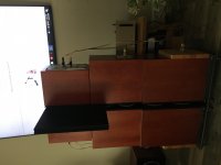
I’ll see if I can do anything with it. Nothing at all out of the side panels on the top modules between 100hz and 2khz, but that’s kind of expected after what I did to them. The lower modules are more conventional, with a vertical brace in each. Easy to try with a digital active system. Sorry about the sideways shot
Attachments

I still own the Dunlavy's, and I obviously know Atkinson's side panel resonance measurements(Pretty severe between 500 and 700hz, but that's relative to a true 91db sensitivity which needs to be taken into account), so I'll see if I can get the panels to sing into the mic while running the 4ohm Nulled(Out of Phase) speakers with 2.83v. I know exactly where to look which will help a lot.
If I can't get it to sing with 2.83v, I'll double it or even triple it. The cool thing is that that the drivers will(should) cancel out no matter how high I take the voltage(Within reason🙂)
If I can't get it to sing with 2.83v, I'll double it or even triple it. The cool thing is that that the drivers will(should) cancel out no matter how high I take the voltage(Within reason🙂)
Last edited:
- Home
- Loudspeakers
- Multi-Way
- Accelerometers to measure panel vibrations?