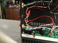
Having an issue with my build. Finished up. Set the bias (one side gave me a bit of trouble reading any volts, but I finally got a connection). Both lights lit up. I’m only getting sound out of the right channel though. Looked over some questionable solder joints and touched up. Not sure what to do now.
Attachments
coolnose and juma, thanks for your answer,
by the way does this mean that I can pump up the volume.
the default sound is quite soft, I would like more volume or is it impossible with this amp.
by the way does this mean that I can pump up the volume.
the default sound is quite soft, I would like more volume or is it impossible with this amp.
can you give some voltage measurements in specific points?
If that question was intended for me, I can....but really don't know how or where. I have a meter, lol.
So, I'm checking DC voltage with the unit on? Both sides of resistors, caps, etc? Is there anything I need to stay away from or can screw up?
I checked all values with meter as I stuffed the boards.
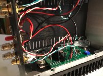
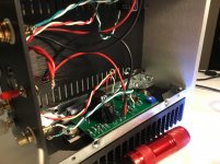
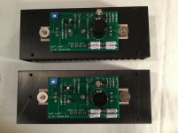
Here’s a shot of the stuffed PCBs from last night.
There were 2 resistors included that weren’t on schematic or build sheet. They were 68.1k.
Here’s a shot of the stuffed PCBs from last night.
There were 2 resistors included that weren’t on schematic or build sheet. They were 68.1k.
Attachments

So, I'm checking DC voltage with the unit on? Both sides of resistors, caps, etc? Is there anything I need to stay away from or can screw up?
Be carefull not to make any shorts with the probes. Maybe a good idea to fix the black probe to gnd and measure DC voltages relative to gnd. Then you have only one probe (red) to concentrate on hitting the "spot".
R13 and R9 seem to be same. The voltage at the resistors on the left channel (one that isn’t working) seem higher than the right channel.
Right channel - resistors R1 through R4 are about 9v
Left channel - resistors R1 through R4 are about 16v
Taken at corresponding places
Left channel - resistors R1 through R4 are about 16v
Taken at corresponding places
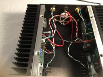
Remove the suspect PCB off the heatsink and re-flow the solder joints around C2, Q3, and that general area. Also the big resistors.
Right channel - resistors R1 through R4 are about 9v
Left channel - resistors R1 through R4 are about 16v
Taken at corresponding places
The 16v is probably the problem. Then you have bias on left channel set to 16v?
Maybe voltages on the Q2 and Q3 pins could tell something. Q2 seems to be driven to hard......but someone with more knowledge on the amp may comment here......
- Status
- Not open for further replies.
- Home
- Amplifiers
- Pass Labs
- ACA V1.5 Illustrated Build Guide