Particularly elegant, and a very good engineering approach to the cooling and the packaging........
Bloody wonderfull!!
HD
Bloody wonderfull!!
HD
Hi N Brock,
Very nice work and amazing thinking to get us away from making a chassis or having to solder any wires. Bravo!
LED cooling is the new CPU cooling. If we look around we can find an easy to use rectangular format 160mm x 68mm x 40mmH heatsink that has predrilled tapped holes and even two copper core heat spreaders and built in fans. Replace the noisy fans with Noctuas and you have something that can easily run with higher power amps dissipating 100w+ per channel. This one is $30 with shipping. The existing tapped holes can be used to clamp a plate or bar that would press the MOSFET body right over the middle of the copper core. No need to use one screw on the MOSFET. Underhung flat mounted MOSFETs can be easily clamped this way using PCB as the clamp. Maybe 2mm thick FRP for more stiffness. A desktop M2 or F6 could probably be realized this way.
https://a.aliexpress.com/_mMsudco

When we look for heatsinks for high power “COB matrix LEDs” the world of affordable heatsinks really opens up. LED heatsinks commodity items that are extruded by the miles I am sure, hence the cost is very low.

Very nice work and amazing thinking to get us away from making a chassis or having to solder any wires. Bravo!
LED cooling is the new CPU cooling. If we look around we can find an easy to use rectangular format 160mm x 68mm x 40mmH heatsink that has predrilled tapped holes and even two copper core heat spreaders and built in fans. Replace the noisy fans with Noctuas and you have something that can easily run with higher power amps dissipating 100w+ per channel. This one is $30 with shipping. The existing tapped holes can be used to clamp a plate or bar that would press the MOSFET body right over the middle of the copper core. No need to use one screw on the MOSFET. Underhung flat mounted MOSFETs can be easily clamped this way using PCB as the clamp. Maybe 2mm thick FRP for more stiffness. A desktop M2 or F6 could probably be realized this way.
https://a.aliexpress.com/_mMsudco
When we look for heatsinks for high power “COB matrix LEDs” the world of affordable heatsinks really opens up. LED heatsinks commodity items that are extruded by the miles I am sure, hence the cost is very low.
Last edited:

Hi Mr. Brock, I wonder whether this is the heatsink you are talking about?
https://www.aliexpress.com/item/32947619807.html
_
Yep, that's the one I got for V0. The new 140mm sinks just arrived yesterday, will update soon about those.
The J111 seems like a great option for this. Thanks everyone for the footprint ideas
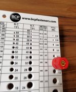
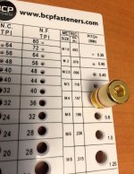
I just bought one of these super-handy thread gauges , a tool I had never heard of until this week. I'm using it to discover the diameter and thread-pitch of some five way binding posts in my miscellaneous parts box. The one in the photo happens to be metric, size "M5". A wholesome, jolly good time.
_
_
Attachments
Hmm... how tall would an F5 v3 Turbo or A2 be using such vertical heatsinks? Would it take a single 20 inch tall Tower Of Power per channel or perhaps several shorter Towers?
They'd be like mini Pipe-o's -with amps like that, my wife might warm up to the idea of a pair of eight foot Pipe-o's in the living room. I mean, she's used to the Maggies already.
Anyhow, back to the vertical heatsinks for the higher powered amps... maybe add a row of them, standing up, next to each other instead of those "boring" standard heat sinks we're so used to. it would make an awesome looking A2.
In the meantime... will this become a kit we can buy? It's really nice, thanks for the great work!
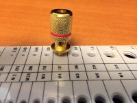
Those are actually my favorite binding posts ... 😀Found some knurled metal (not hex head plastic) binding posts, whose termination bolt is metric size M4.
_
Regards, Claas
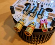
I also like the RCA jacks, I buy them in the bag of 50 for $5. Signal doesn’t know the difference. 🙂
I also like the RCA jacks, I buy them in the bag of 50 for $5. Signal doesn’t know the difference. 🙂
Where do I find that great deal?
N Brock,
Possibly Aliexpress:
https://www.aliexpress.com/item/32795021133.html
https://www.aliexpress.com/item/4001040628341.html
https://www.aliexpress.com/item/1005003336925648.html
Close to the price point X has mentioned...one cannot help but wonder how can the price be so low.
Possibly Aliexpress:
https://www.aliexpress.com/item/32795021133.html
https://www.aliexpress.com/item/4001040628341.html
https://www.aliexpress.com/item/1005003336925648.html
Close to the price point X has mentioned...one cannot help but wonder how can the price be so low.
Yes, those are the ones. I think Zman01 has found an even better price at $0.57 for 10. 🙂
For my nicer projects I will use these though, equivalent of 45 of the cheap ones!

For my nicer projects I will use these though, equivalent of 45 of the cheap ones!
Hey,Yes, those are the ones. I think Zman01 has found an even better price at $0.57 for 10. 🙂
For my nicer projects I will use these though, equivalent of 45 of the cheap ones!
View attachment 1020007
I want me some of those, they look nice, where did you get them from?
I really like this project, and because imitation is the sincerest form of flattery, I copied it 🙂
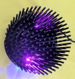
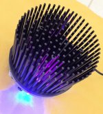
I added two upward facing pink LEDs (Mouser P/N 604-WP7113VRVC1C) to illuminate the black pin fins, and also a "breathing" blue LED (sold HERE) for the On/Off pilot light.
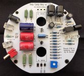
I added a "PO89ZB" power supply filter circuit (LINK) on the round PCB, to remove switching power supply noise. The filter components are in the top right corner of the board, at 2 o'clock.
Finally, I got rid of the expensive 2SK170 / LSK170, and replaced it with a Fairchild J112 which costs less than $0.65.
A huge thank-you to Nelson Brock for inventing and unveiling this project! I hope he decides to make it available to diyAudio members in some way, possibly bare boards, or partial kits, or full kits, or downloadable Gerber files. He deserves to be economically rewarded for his hard work.
However, if he decides not to, and if he gives his permission, I'll make this "RACAM" available to members. Probably in a new thread.
Mark Johnson
(8 attachments below, schematic is the last one)
I added two upward facing pink LEDs (Mouser P/N 604-WP7113VRVC1C) to illuminate the black pin fins, and also a "breathing" blue LED (sold HERE) for the On/Off pilot light.
I added a "PO89ZB" power supply filter circuit (LINK) on the round PCB, to remove switching power supply noise. The filter components are in the top right corner of the board, at 2 o'clock.
Finally, I got rid of the expensive 2SK170 / LSK170, and replaced it with a Fairchild J112 which costs less than $0.65.
A huge thank-you to Nelson Brock for inventing and unveiling this project! I hope he decides to make it available to diyAudio members in some way, possibly bare boards, or partial kits, or full kits, or downloadable Gerber files. He deserves to be economically rewarded for his hard work.
However, if he decides not to, and if he gives his permission, I'll make this "RACAM" available to members. Probably in a new thread.
Mark Johnson
(8 attachments below, schematic is the last one)
Attachments
-
 Topside_no_xitors.jpg273.2 KB · Views: 831
 -
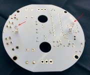 Bottom_no_Xitors.jpg183.1 KB · Views: 581
 -
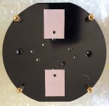 Thermal_Pads.jpg187.5 KB · Views: 518
 -
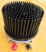 rear_view.jpg201.9 KB · Views: 1,627
 -
 Pink_glow.jpg213 KB · Views: 907
 -
 Blue_Pilot.jpg221.6 KB · Views: 3,465
 -
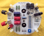 Ckt_Stuffed.jpg214.3 KB · Views: 2,602
 -
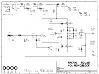 RACAM_schematic_revA_2022_Feb_19.png27.2 KB · Views: 2,866
Last edited:
Nice work, Mark. Good idea to add the filter. What current are those inductors rated for?
I think these style of amps could be called ACA Hedgehogs. 🙂
I think these style of amps could be called ACA Hedgehogs. 🙂
- Home
- Amplifiers
- Pass Labs
- ACA Redux