Hi,
I previously built an ACA 1.6 biased at 1.2A with a 24vdc switching supply.
Sounded so good, I wanted a more powerful version for my 4 ohm speakers.
I built a pair of ACA monoblocks. Scratch built, not kit.
I used larger heatsinks, and a beefier switching power supply.
I bought a pair of Meanwell 36vdc@4.44A switching power supplys, and my plans were to bias the amps at 18vdc,(midpoint), and 2.2 amps current, by adjusting R1,R2,R3,R4 to get 2.2 amps current.
Am I correct in assuming power delivered to my 4 ohm speakers will be about 19 watts peak? Is the correct calculation: (I^2)*Z or 4.84 * 4 ohms = 19 watts peak? If so, would RMS power then be .7 * 19 = aprox. 13.3 watts?
I cannot find a clear,(to me), description of power calculation for a class A amp, based on voltage and current at the output.
Any help appreciated.
Calculations sounds ok, but it is the perfect world.
Max undistorted peak voltage from the amp is the lead. This Vout^ swings pos and neg so max Vout is Vout^^. Veff out ~ V^^ /3 and from there divide by current draw from load.
An audio amplifier is a voltage source (low output imedance), not a current source.
So what really counts in the end is if the voltage source is capable of sourcing and sinking the requested or dumped current from the load, GIVEN the applied momentary voltage applied to this load.
A rule of thumb (all effective sinus values), and as an example:
20W - 8Ω -> 12.6V / 1.58A --> 160WΩ
40W - 4Ω -> 12.6V / 3.16A --> 160WΩ
80W - 2Ω -> 12.6V / 6.32A --> 160WΩ
"The product of power and load is a constant."
(Law of Mars Bravo, coined!)
A voltage source provides the needs of the load whatsoever.
Check for commercial and other designs and 'realisations'.
Those particular SMPS may not be the best choice for powering amp to drive 4 Ohm speakers. Notice from the data above that more current is needed for lower impedance speakers. I’ve seen SMPS struggle with high current class A amplifiers.
My recommendation would be a linear PSU based on a 300VA transformer that can source at least 6.8 Amps per channel. Eight Amps would be better; reduce the voltage to get the necessary current rating.
My recommendation would be a linear PSU based on a 300VA transformer that can source at least 6.8 Amps per channel. Eight Amps would be better; reduce the voltage to get the necessary current rating.
Changing R1,R2,R3,R4 is not advisable, it will change the THD of the ACA. It is better to simply adjust R15 but keep an eye on the dissipation of R1-R4.
Changing R1 through R4 by a small amount works well, especially to help boost the current. I prefer leaving R1 and R2 at 0.47, and changing R3 and R4 to 0.56 Ohms. There are a few other combinations of R3 and R4 that have a close parallel resistance. R15 can then be set to achieve the desired quiescent current.
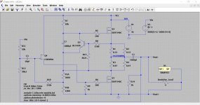
It's perhaps not as good as might be thought. Admittedly just a simulation based on the original (which to be fair comes out pretty close to the published specs).
This is running 2.4A with the midpoint optimised for symmetrical clipping. The clipping never looks symetrical.
This is running 2.4A with the midpoint optimised for symmetrical clipping. The clipping never looks symetrical.
Attachments

Another thing that is worth trying in a higher current ACA is using different Mosfets. The upper one (Q2) is a good place to use an IRFP044. I have already tried an IRFP140 at Q1, and like the way that sounds.
> 1.2A with a 24vdc
> for my 4 ohm speakers.
> 36vdc.... 2.2 amps current
24V 1.2A idle is clearly 28.8W dissipation. It *ideally* supports 12V 2.4V peak. The optimum load is 12V/2.4A or 5 Ohms; the max SineRMS power is 12V*2.4A/2 or 14.4 Watts
If worked into 8 Ohms the idle is unchanged but the 12V peak now sucks 12V/8r or 1.5A peak, which makes 12V*1.5A/2= 9 Watts SineRMS.
Optimum idle current for 36V supply and 4 Ohm load is like 2.25A so "2.2A" is fine. (Your "4" is surely 3.5r to 20+r.) Dissipation is clearly 36V*2.2A or 80W. 2.2A idle makes 4.4A peak. 4.4A peak in 4r is 17.6V, in sight of 18V. Power output 17.6*4.4A/2= 38 Watts SineRMS.
----------------------------------
> ...would RMS power then be .7 * 19 = aprox. 13.3 watts?
Return to chapter 1 in your textbooks. 0.707 for Voltage. Power is 0.707^2 or 0.5.
ACA power
Thanks to all for your help.
From PRR:
"Optimum idle current for 36V supply and 4 Ohm load is like 2.25A so "2.2A" is fine. (Your "4" is surely 3.5r to 20+r.) Dissipation is clearly 36V*2.2A or 80W. 2.2A idle makes 4.4A peak. 4.4A peak in 4r is 17.6V, in sight of 18V. Power output 17.6*4.4A/2= 38 Watts Sine RMS. "
That is encouraging:
80 watts dissipation is high, but I am using 2 "stereo" cabinets as monoblocks, with Q1 and Q2 on individual heatsinks. Would be 40 watts per heatsink on each monoblock amp.
mg16
Changing R1 through R4 by a small amount works well, especially to help boost the current. I prefer leaving R1 and R2 at 0.47, and changing R3 and R4 to 0.56 Ohms. There are a few other combinations of R3 and R4 that have a close parallel resistance. R15 can then be set to achieve the desired quiescent current.
In general, reducing R3 and R4 increases THD because it reduces drive to Q2 via C2. For lowest THD, the R3, R4 parallel combination needs to be .82 Ohms and the R1, R2 combination needs to be .15 Ohms. Adjust R15 to restore idle current. See my posts #274 and #284 in the ACA thread.
I think the ACA sounds better the way Nelson designed it, but the linearized version might be useful as a unity gain inverting side in a bridge drive setup. That would preserve the even harmonic THD.
- Home
- Amplifiers
- Pass Labs
- ACA power calculation