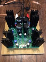
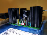
Finished tweaking the bias today after getting a sense of how much it drifted after some warmupand hooked it up in my second system.
Unfortunately, while it makes music, one channel is significantly louder than the other. I’ll be digging into that in the main thread, but wanted to present one more completed amp.

Unfortunately, while it makes music, one channel is significantly louder than the other. I’ll be digging into that in the main thread, but wanted to present one more completed amp.

Thank you Kevin for fantastic GB - received the Board / Mosfets today and thanks to Mark for providing the PCB. Wondering where can I see the BOM
kannan
kannan
R2 and R3 should be 221K. I can't make out the values the way they are oriented on the board. Let that be a lesson to all builders. Can you verify the values?Finished tweaking the bias today after getting a sense of how much it drifted after some warmupand hooked it up in my second system.
Unfortunately, while it makes music, one channel is significantly louder than the other. I’ll be digging into that in the main thread, but wanted to present one more completed amp.
Last edited:
Yes, R2 & R3 are 221K for both channels. FWIW, all resistors are installed with the values clearly visible.R2 and R3 should be 221K. I can't make out the values the way they are oriented on the board. Let that be a lesson to all builders. Can you verify the values?
Another board and Fets have safely arrived! If all goes well I will have started my journey to become a Fearless Amplifier Builder by next weekend. I checked all the parts against the BOM and tested values of all the resisters last night. It’s my daughter’s birthday so probably won’t be able to hit the solder station for another week.
Thanks again to Kevin for organizing this effort and our Papa for donating the Harris Fets!

Thanks again to Kevin for organizing this effort and our Papa for donating the Harris Fets!
BOM listed in Nelson's article (Part 1) in 1st post of ACA mini thread:
https://www.diyaudio.com/community/threads/diy-aca-mini.379037/
There might be some mods that members recommend, but I haven't dug through all the posts to discover them. 6L6 and others suggest building our toys as stock, and then trying out variations. All part of the fun and the adventure. Cheers, - David
Not listed in the BOM, as pointed out earlier in this thread, are the jumper headers and jumpers/shunts themselves.BOM listed in Nelson's article (Part 1) in 1st post of ACA mini thread:
https://www.diyaudio.com/community/threads/diy-aca-mini.379037/
There might be some mods that members recommend, but I haven't dug through all the posts to discover them. 6L6 and others suggest building our toys as stock, and then trying out variations. All part of the fun and the adventure. Cheers, - David
I had both on hand, so I can't suggest specific part numbers.
I was able to source everything from Mouser this morning and place an order. Some slight variations on a few items compared to the article BOM, but I think I was able to match substitutions within spec. Excited to build this one.
There were five separate orders needed for the aca mini build. Got it all right except for the 3/4 ohm resistors (missed it by that much). They have been ordered and should be here this week.
Anyway, it surprised me that this clone board isn't exactly like the board in Nelson's pdf or in 6L6's build guide. The LED resistor has moved to under the smaller caps and now resides with the bank of 4 other resistors. Not much of a change really but it made me take notice.
The direction of the FET's has also changed ... in the original artwork the two pairs face different directions but the clone board has both sides to be installed in the same direction. Is this also a matter of being tidy?
Is this just part of the evolution of the board as the project matures?
Sounds like you are genuinely surprised that the "Almost Clone" PCB is not an exact duplicate of the one in Nelson Pass's pdf document. Almost Clone. Almost. Hmmm.
Have a look at a thread from December 2021, in the Swap Meet forum. Title was "Free PCB: Clone of ACA Mini -- to a good home"
_
Have a look at a thread from December 2021, in the Swap Meet forum. Title was "Free PCB: Clone of ACA Mini -- to a good home"
_
Attachments
Sounds like you are genuinely surprised that the "Almost Clone" PCB is not an exact duplicate of the one in Nelson Pass's pdf document. Almost Clone. Almost. Hmmm.
Never really contemplated the word Almost, just the word clone. For the 50 boards offered in the group buy it seemed likely they would be made using the original artwork. That would have been the quickest and easiest path.
Obviously there's nothing wrong with the clone board and I'm tickled to have gotten one. Just surprised someone went to all the trouble.
🙂
A Huge Thank you too Kevin and Nelson Pass for this incredible amp the Video was a big help with the Bias .
It bought back memories of my F5 bias !
Thanks again everyone! very nice sounding enjoying the Music! working well with a H2 generator as a pre-amp yet even more PaPa awesomeness!
It bought back memories of my F5 bias !
Thanks again everyone! very nice sounding enjoying the Music! working well with a H2 generator as a pre-amp yet even more PaPa awesomeness!
Attachments
** Also, note!!! 4 1000 uF caps are needed, not 3 as printed in the BOM for C4, C5.Not listed in the BOM, as pointed out earlier in this thread, are the jumper headers and jumpers/shunts themselves.
I had both on hand, so I can't suggest specific part numbers.
Jumper headers:
https://www.mouser.com/ProductDetail/Wurth-Elektronik/62001011121?qs=ljCeji4nMDmfeXuFwGbNKQ==
Just be sure to put them in a baggy when you cut them as the clipped pieces fly away into the vast unknown.
Jumpers:
https://www.amazon.com/dp/B077957RN7?psc=1&ref=ppx_yo2_dt_b_product_details
I believe Mark supplied this link earlier. I now have a lifetime supply so if you need a few and are in the US send me a pm with your address.
I use two pair of needle-nose pliers to separate those "breakaway header" sticks, into pieces with exactly two pins. One pair of pliers on the left of the V-cut valley, the other pair on the right. Bend slowly and voila, the plastic breaks along the V-cut. You are holding the freshly cut two-pin piece in one pliers, and the remaining stick in the other pliers. Nothing flies away, nothing falls to the floor, nothing jams the vacuum cleaner.
Parts received and the almost clone has gone from almost done to actually done. Put two of the mosfets in the wrong place and the LED just sat and blinked madly. Finding the issue and fixing it made it work. It biases and sounds OK. Any learned thoughts on if the out of place mosfets were damaged? They weren't on for very long.
It's got a few hours on it and it's already sounding good. It was kinda bassy at first but that seems to be tightening up and improving nicely. Time for tunes!
A great big thanks to papa (again) for such a nice project. Another thanks to Kevin for doing the almost group buy and to 6L6 for the great build guides. This is a wonderful place.
It is hooked to a pair of 4 pi speakers with a Whammy (with a 2107 opamp) as preamp. It sounds great.
Attachments
Hi, I'm not able to find the main capacitors in stock at Mouser, 3 only available,
can I take this one with 25mm external diameter instead 22mm ?
SLPX153M025C7P3
Thank you
Matteo
can I take this one with 25mm external diameter instead 22mm ?
SLPX153M025C7P3
Thank you
Matteo
Measure the diameter of the circles (capacitor body footprints) that are silk screened on the top side of your PCB. How much bigger or smaller are those circles, than 25 mm?
Also measure the lead-to-lead hole spacing on your PCB. (Center of hole to center of hole). Do the replacement caps match that lead spacing?
Also measure the lead-to-lead hole spacing on your PCB. (Center of hole to center of hole). Do the replacement caps match that lead spacing?
- Home
- Group Buys
- ACA Mini "Almost Clone" Board